
Installation Instructions Comfort Bridge Models


25
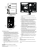
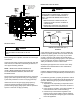
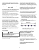
counterflow MoDel InstalleD HorIZontallY wItH
left sIDe Down
* Also see Front Cover Pressure Switch Tube Location on
page 9.
Minimum 5 ½” clearance is required for the drain trap
beneath the furnace.
Hose #4
Hose #5
Hose #4
Hose #2
fIgure 31
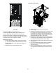
1. Remove the factory installed drain trap and hose
assemblies. Leave the 100° elbow inserted and
clamped in the vent-drain elbow.
2. Remove two 1”plugs from left side of cabinet
3. Drain the Collector Box. Remove the cap from the
left side of the collector box drain port (bottom in
horizontal left position) and install it on right side drain
port.
4. Place radius end of hose #4 (factory installed) on
the collector box drain port and secure with a silver
clamp.
5. Insert hose #2 from outside the cabinet in the front
drain hole.
6. Connect hose #4 & hose #2 together using a straight
barbed coupling and two gold clamps (factory
installed).
7. (Draining the Vent Elbow) Remove rubber plug from
vent – drain elbow side port.
8. The un-used vent-drain elbow drip leg port must
be plugged to prevent ue gases from escaping.
Insert rubber plug removed in step 7 into the 100°
elbow. (Inserting a blunt tool such as a 3/16” Allen
wrench into the center of the rubber plug will stretch
the plug and allow complete insertion).
9. Place radius end of hose #4 on the side port of vent –
drain elbow and secure with a gold clamp.
10. Insert a ½” diameter PVC pipe (factory installed) into
hose #4 and secure with a gold clamp.
11. Insert the non-grommet end of hose #5 (factory
installed) from outside the cabinet in the back drain
hole.
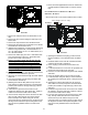
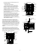
counterflow MoDel InstalleD HorIZontallY wItH
rIgHt sIDe Down
Minimum 5 ½” clearance is required for the drain trap
beneath the furnace.
note: for HorIZontal InstallatIons, soMe of tHe
requIreD Hoses are founD In tHe factorY-InstalleD
Hose asseMBlIes. reMoVe tHe Hose claMPs to oBtaIn
tHe resPectIVe Hoses neeDeD for InstallatIon, anD
Install Per tHe followIng DIrectIons.
fIgure 30
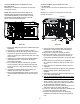
1. Remove the drain trap and factory installed drain tube
assemblies.
2. Remove two 1” plugs from right side of cabinet
3. (Draining the Collector Box) From outside the cabinet,
insert the non-grommet end hose #7 into the back
drain hole and secure to collector box drain port using
a silver clamp.
4. (Draining the Vent Elbow) Insert the straight barbed
coupling into the vent – drain elbow drip leg and
secure with a red clamp.
5. From outside the cabinet, insert the non-grommet
end of hose #8 into the front cabinet drain hole and
secure on the vent - drain elbow barb tting using a
red clamp.
6. Using the two sheet metal screws provided in the
cabinet, secure the trap to the furnace.
7. Refer to Field Supplied Drain section for instructions
on eld supplied / installed drain on outlet of furnace
trap.