
Install Instructions


6
- hydrochloric acid
- carbon tetrachloride
- cements and glues
- deicing salts or chemicals
- halogen type refrigerants
- antistatic fabric softeners for clothes dryers
- masonry acid washing materials
• Isolate a non-direct vent furnace if it is installed near an
area frequently contaminated by any of the above
substances. This protects the non-direct vent furnace
from airborne contaminants. To ensure that the
enclosed non-direct vent furnace has an adequate supply
of combustion air, vent from a nearby uncontaminated
room or from outdoors. Refer to the Combustion and
Ventilation Air Requirements for details.
• If the furnace is used in connection with a cooling coil
unit, install the furnace upstream or in parallel with
the cooling coil unit. Premature heat exchanger failure
will result if the cooling unit is placed ahead of the
furnace.
For vertical (upflow or downflow) applications, the
minimum cooling coil width shall not be less than
furnace width minus 1”. Additionally, a coil installed
above an upflow furnace or under a counterflow furnace
may be the same width as the furnace or may be one
size larger than the furnace.
Example: a “C” width coil may be installed with
a “B” width furnace.
For upflow applications, the front of the coil and furnace
must face the same direction.
• If the furnace is installed in a residential garage,
position the furnace so that the burners and ignition
source are located not less than 18 inches (457 mm)
above the floor. Protect the furnace from physical
damage by vehicles.
• If the furnace is installed horizontally, ensure the
access doors are not on the “up/top” or “down/
bottom” side of the furnace.
• Do not connect this furnace to a chimney flue that
serves a separate appliance designed to burn solid
fuel.
• On Counterflow Installations, the air conditioning
coil must be downstream on the supply (positive)
side of the furnace heat exchanger.
• Counterflow Installation over a noncombustible
floor. Before setting the furnace over the plenum
opening, ensure the surface around the opening is
smooth and level. A tight seal should be made
between the furnace base and floor by using a
silicone rubber caulking compound or cement grout.
• Counterflow Installation over a combustible floor.
If installation over a combustible floor becomes
necessary, use an accessory subbase (see
Specification Sheet applicable for your model for
details.) A special accessory subbase must be used
for upright counterflow unit installations over any
combustible material including wood. Refer to
subbase instructions for installation details. Follow the
instructions with the subbase for proper installation.
Do not install the furnace directly on carpeting, tile,
or other combustible material other than wood flooring.
NOTE: A subbase will not be required if an air conditioning
coil is installed between the supply air opening on the furnace
and the floor.)
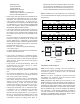
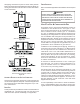
POSITION* SIDES REAR FRONT BOTTOM FLUE TOP
Upflow 0" 0" 3" C 0" 1"
Horizontal 6" 0" 3" C 0" 6"
C = If placed on combustible floor, floor MUST be wood only.
*MVC96 MINIMUM CLEARANCES TO COMBUSTIBLE MATERIALS
(INCHES)
POSITION* SIDES REAR FRONT BOTTOM FLUE TOP
Counterflow 0" 0" 3" NC 0" 1"
Horizontal 6" 0" 3" C 0" 6"
C = If placed on combustible floor, floor MUST be wood only.
NC = For installation on non-combustible floors only. A combustible subbase
must
b
e use
d
f
or
i
nsta
ll
at
i
ons on com
b
ust
ibl
e
fl
oor
i
ng.
*CVC96 MINIMUM CLEARANCES TO COMBUSTIBLE MATERIALS
(INCHES)
TOP
BOTTOM
TOP
BOTTOM
Counterflow
Figure 1
CLEARANCES AND ACCESSIBILITY
NOTE: For servicing or cleaning, a 24” front clearance is
required. Unit connections (electrical, flue and drain) may
necessitate greater clearances than the minimum
clearances listed above.
NOTE: In all cases, accessibility clearance must take
precedence over clearances from the enclosure where
accessibility clearances are greater.
NOTE: Installations must adhere to the clearances to com-
bustible materials to which this furnace has been design cer-
tified. The minimum clearance information for this furnace is
provided on the unit’s clearance label. These clearances must
be permanently maintained. Clearances must also accommo-
date an installation’s gas, electrical, and drain trap and drain
line connections. If the alternate combustion air intake or
vent/flue connections are used additional clearance must be
provided to accommodate these connections. Refer to Vent/
Flue Pipe and Combustion Air Pipe for details.