
Installation Guide


10
Figure 3B
Fibure 3C
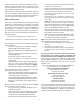
Recommended Installation Positions
ALTERNATE ELECTRICAL AND GAS LINE CONNECTIONS
This furnace has provisions allowing for electrical and gas line
connections through either side panel. In horizontal applications
the connections can be made either through the “top” or “bot-
tom” of the furnace.
DRAIN PAN
A drain pan must be provided if the furnace is installed above a
conditioned area. The drain pan must cover the entire area
under the furnace (and air conditioning coil if applicable).
FREEZE PROTECTION
Refer to Horizontal Applications and Conditions - Drain Trap and
Lines.
P
ROPANE
G
AS
/H
IGH
A
LTITUDE
I
NSTALLATIONS
WARNING
P
OSSIBLE
PROPERTY
DAMAGE
,
PERSONAL
INJURY
OR
DEATH
MAY
OCCUR
IF
THE
CORRECT
CONVERSION
KITS
ARE
NOT
INSTALLED
. T
HE
APPROPRIATE
KITS
MUST
BE
APPLIED
TO
ENSURE
SAFE
AND
PROPER
FURNACE
OPERATION
. A
LL
CONVERSIONS
MUST
BE
PERFORMED
BY
A
QUALIFIED
INSTALLER
OR
SERVICE
AGENCY
.
This furnace is shipped from the factory configured for natural
gas at standard altitude. Propane gas installations require an
orifice and orifice change to compensate for the energy content
difference between natural and propane gas.
High altitude installations may require both a pressure switch
and an orifice/spring change. These changes are necessary to
compensate for the natural reduction in the density of both the
gas fuel and the combustion air at higher altitude.
For installations above 7000 feet, please refer to the furnace
Specification Sheets for required kit(s).
High
Stage
Low
Stage
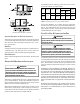
Natural None #45 3.5" w.c. 1.9" w.c. None
Propane
LPM -08*
1
1.25mm 10.0" w.c. 6.0" w.c. None
0-7000
1
LPM -08* supports both Honeywell and White-Rodgers 2-stage valves
NOTE:
In Canada, gas furnaces are only certified to 4500 feet.
Gas Altitude Kit Orifice
M anifold Pressure
Pressure
Switch
Change
Contact the distributor for a tabular listing of appropriate
manufacturer’s kits for propane gas and/or high altitude instal-
lations. The indicated kits must be used to insure safe and
proper furnace operation. All conversions must be performed by
a qualified installer, or service agency.
V
ENT
/F
LUE
P
IPE
& C
OMBUSTION
A
IR
P
IPE
F
AILURE
TO
FOLLOW
THESE
INSTRUCTIONS
CAN
RESULT
IN
BODILY
INJURY
OR
DEATH
. C
AREFULLY
READ
AND
FOLLOW
ALL
INSTRUCTIONS
GIVEN
IN
THIS
SECTION
.
WARNING
U
PON
COMPLETION
OF
THE
FURNACE
INSTALLATION
,
CAREFULLY
INSPECT
THE
ENTIRE
FLUE
SYSTEM
BOTH
INSIDE
AND
OUTSIDE
OF
THE
FURNACE
TO
ASSURE
IT
IS
PROPERLY
SEALED
. L
EAKS
IN
THE
FLUE
SYSTEM
CAN
RESULT
IN
SERIOUS
PERSONAL
INJURY
OR
DEATH
DUE
TO
EXPOSURE
TO
FLUE
PRODUCTS
,
INCLUDING
CARBON
MONOXIDE
.
WARNING
A condensing gas furnace achieves its high level of efficiency by
extracting almost all of the heat from the products of combus-
tion and cooling them to the point where condensation takes
place. Because of the relatively low flue gas temperature and
water condensation requirements, PVC pipe is used as venting
material.
In addition to PVC and ABS pipe and fittings, Innoflue
®
by
Centrotherm Eco Systems and PolyPro
®
by M&G Duravent are
also approved vent and combustion air materials for instal-
lations in the U.S.A. and Canada. Manufacturers Installation
instructions for these products must be followed. These prod-
ucts have specific instructions for installing, joining and ter-
minating. Do not mix materials or components of one manu-
facturer with materials or components of another manufac-
turer.
All furnaces are built with 2" vent / intake pipe and connec-
tors. For furnaces requiring installation of 3" pipe, the tran-
sition from 2" to 3" should be done as close to the furnace as
practically possible.