
Install Instructions


13
Canada. If ABS is used as a combustion air pipe, it must be
CSA certified. Always follow the manufacturer’s instructions
in the use of primer and cement. Do not use primer and
cement around potential sources of ignition. Do not use
primer or cement beyond its expiration date.
The safe operation, as defined by ULC S636, of the vent
system is based on following these installation instructions,
the vent system manufacturer’s installation instructions, and
proper use of primer and cement. It is recommended under
this standard, that the vent system be checked once a year
by qualified service personnel. All fire stops and roof flashings
used with this system must be UL listed. Acceptability under
CAN/CSA B149.1-15 is dependent upon full compliance with
all installation instructions. Consult the authority having
jurisdiction (gas inspection authority, municipal building de-
partment, fire department, etc.) before installation to de-
termine the need to obtain a permit. *IPEX System 636™ is a
trademark of IPEX Inc.
Carefully follow the pipe manufacturers’ instructions for cut-
ting, cleaning, and solvent cementing PVC and/or ABS.
The vent can be run through an existing unused chimney
provided the space between the vent pipe and the chimney
is insulated and closed with a weather-tight, corrosion-re-
sistant flashing.
STANDARD FURNACE CONNECTIONS
It is the responsibility of the installer to ensure that the piping
connections to the furnace are secure, airtight, and adequately
supported.
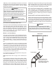
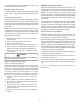
VENT/FLUE P IPE
The vent pipe outlet is sized to accept 2” pipe. Secure
vent/flue pipe directly into the furnace fitting with the ap-
propriate glue. Alternately, a small section of 2" pipe may
be glued in the furnace socket and a rubber coupling in-
stalled to allow removal for future service. Combustion Air
and Vent piping should be routed in a manner to avoid con-
tact with refrigerant lines, metering devices, condensate
drain lines, etc. If necessary, clearances may be increased
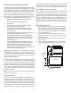
by creating an offset using two 45 degree elbows. This
joint can be rotated on the fitting to establish maximum
clearance between refrigerant lines, metering devices, and
condensate drain lines, etc. This joint is the equivalent of
one 90 deg. elbow when considering elbow count. (See Fig-
ure 8)
VENT-DRAIN
Figure 8
NOTE: For non-direct vent installations, a minimum of one
90° elbow should be installed on the combustion air intake
coupling to guard against inadvertent blockage.
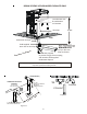
COMBUSTION AIR PIPE
DIRECT VENT INSTALLATIONS
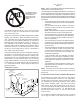
E
DGES
OF
SHEET
METAL
HOLES
MAY
BE
SHARP
. U
SE
GLOVES
AS
A
PRECAUTION
WHEN
REMOVING
HOLE
PLUGS
.
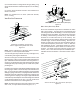
WARNING
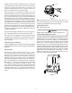
On upflow units secure the combustion air intake pipe to the air
intake coupling by using a take apart rubber coupling supplied
with the furnace or a plastic coupling. Also, the intake cou-
pling may be inverted to allow the intake pipe to be glued
directly to it. After inverting the coupling, secure it to the
furnace top with screws. On counterflow units secure the com-
bustion air intake pipe to the air intake coupling using the rubber
coupling and worm gear hose clamps provided with the unit. The
counterflow rubber coupling allows service removal of air intake
piping internal to the furnace blower compartment. The com-
bustion air intake pipe can also be secured directly to the
counterflow unit air intake pipe coupling.
Figure 9