
Install Instructions


22
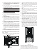
5. (Draining the Vent Elbow) Locate hose #6. Measuring
from the non-grommet end; cut off and discard 1 ½” for
a “D” width cabinet, 5” for a “C” width cabinet, 8 ½”
for a “B” width cabinet.
6. Remove the rubber plug from vent – drain elbow side
port. Place hose #6 on the vent – drain elbow side port
and secure with a silver clamp .
7. Unused vent-drain elbow drip leg port must be sealed
to prevent flue gases from escaping. Insert the rubber
plug removed in Step 6 into the unused elbow drain
port; Inserting a blunt tool such as a 3/16” Allen
wrench into the center of the rubber plug will stretch
the plug and allow complete insertion.
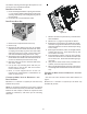
8. Locate hose #5 and cut 3” from the non-grommet end.
Discard the section without the grommet.
9. Insert the cut end of tube #5 through the lower cabinet
drain hole.
10. Connect hose #6 & hose #5 using 100º elbow and secure
with two red clamps
11.(Draining the Collector Box) Remove cap from left side
collector box drain port (bottom in horizontal left position)
and install it on the right side (top) collector box drain
port.
12. Install the non-grommet end of hose #11 from outside
the cabinet in the upper drain hole. Install on collector
box and secure with a silver clamp.
13.Use two silver clamps and secure the hoses to drain
trap. The trap outlet faces the front of the furnace.
Secure the trap to the cabinet using two screws
removed in step 2 by inserting the two screws through
the large set of holes in the top mounting tabs of the
trap into the two predrilled holes in the side of the
cabinet.
14. Refer to Field Supplied Drain section for instructions on
field supplied / installed drain on outlet of furnace trap.
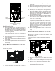
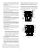
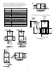
UPFLOW MODEL INSTALLED HORIZONTALLY WITH LEFT SIDE
DOWN - ALTERNATE
* Also see the Front Cover Pressure Switch Tube Location.
Insert flange. Cut 2 ½” long.
R 000142F
Figure 27
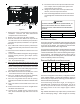
1. (Draining the RF000142 Coupling) Locate hose #2
(factory installed). Cut off and discard the 45°radius
end.
2. Install 90°radius end of hose #2 on RF000142 drain
outlet and secure with a red clamp.
3. Insert coupling in hose #2 and secure with a red
clamp.
4. Locate hose #5 and cut 3" from the non-grommet
end.
Discard the section without the grommet.
5. Insert the cut end of tube #5 through the lower
cabinet drain hole.
6. Insert 100 degree elbow in the cut end of hose #5.
7. Locate hose #6. Using red clamps, connect between
the coupling and 100 degree elbow, cutting off excess
tubing.
8. (Draining the Collector Box) Remove cap from left
side collector box drain port (bottom in horizontal
left position) and install it on right side (top)
collector box drain port.
9. Install the non-grommet end of hose #11 from
outside the cabinet in the upper drain hole. Install
on collector box and secure with a silver clamp.
10. Use two silver clamps and secure the hoses to drain
trap. The trap outlet faces the front of the furnace.
Secure the trap to the cabinet using two screws
removed in step 2 by inserting the two screws
through the large set of holes in the top mounting
tabs of the trap into the two predrilled holes in the
side of the cabinet.
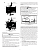
Hose #4 x 3
Hose #5
Figure 28
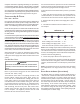
COUNTERFLOW MODEL INSTALLED VERTICALLY
The furnace drain may exit the right or left side of the fur-
nace cabinet (left side preferred) Trap and factory installed
hoses remain as shipped if the drain will exit the left side of