
Install Instructions


23
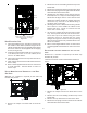
the cabinet. Draining from the right side requires re-loca-
tion of the trap to outside the cabinet.
DRAIN EXITING LEFT SIDE
1. Install a field supplied rubber coupling secured with
a 1 1/4” clamp to enable removing the trap for future
cleaning. Alternately, a PVC fitting may be glued on
the trap outlet.
2. Install drain per local and National codes.
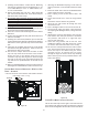
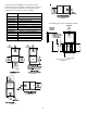
DRAIN EXITING RIGHT SIDE
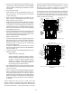
Figure 29
1. Remove hose clamps and hoses from trap.
2. Remove trap.
3. (Draining the Vent Elbow) Insert the non-grommet
end hose #10 into the cabinet back drain hole. Insert
a coupling into the drip leg of the vent-drain elbow
and secure with a silver clamp. Secure hose #10 on
vent-drain elbowbarb fitting with a silver clamp.
4. (Draining the Collector Box) Insert non-grommet end
of hose #9 into the cabinet front drain hole and secure
on collector box drain port with a silver clamp.
5. Mate the drain trap inlets to the hoses and secure
with silver clamps.
6. Line up the trap mounting holes with the pre-
drilled holes in the furnace and secure with 2
screws removed in step 2.
7. Refer to Field Supplied Drain section for
instructions on field supplied / installed drain on
outlet of furnace trap.
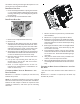
COUNTERFLOW MODEL INSTALLED HORIZONTALLY WITH
RIGHT SIDE DOWN
Minimum 5 ½" clearance is required for the drain trap
beneath the furnace.
NOTE: For horizontal installations, some of the required
hoses are found in the factory-installed hose assemblies.
Remove the hose clamps to obtain the respective hoses
needed for installation, and install per the following
directions.
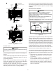
Hose #8
Hose #7
Figure 30
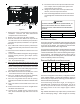
1. Remove the drain trap and factory installed drain
tube assemblies.
2. Remove two 1” plugs from right side of cabinet
3. (Draining the Collector Box) From outside the cabinet,
insert the non-grommet end hose #7 into the back
drain hole and secure to collector box drain port using
a silver clamp.
4. (Draining the Vent Elbow) Insert the straight barbed
coupling into the vent – drain elbow drip leg and
secure with a red clamp.
5. From outside the cabinet, insert the non-grommet
end of hose #8 into the front cabinet drain hole and
secure on the vent - drain elbow barb fitting using a
red clamp.
6. Using the two sheet metal screws provided in the
cabinet, secure the trap to the furnace.
7. Refer to Field Supplied Drain section for instructions
on field supplied / installed drain on outlet of furnace
trap.
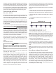
COUNTERFLOW MODEL INSTALLED HORIZONTALLY WITH LEFT
SIDE DOWN
* Also see Front Cover Pressure Switch Tube Location on
page 9.
Minimum 5 ½" clearance is required for the drain trap
beneath the furnace.