
Install Instructions

38
Canada, follow approved purging methods in CAN/CSA B149.1-
15.
Check for leaks using an approved chloride-free soap and water
solution, an electronic combustible gas detector, or other ap-
proved method. Verify that all required kits (propane gas, high
altitude, etc.) have been appropriately installed.
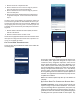
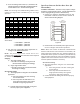
FURNACE STARTUP
1. Close the manual gas shutoff valve external to the furnace.
2. Turn off the electrical power to the furnace.
3. Set the room thermostat to the lowest possible setting.
4. Remove the burner compartment door.
NOTE: This furnace is equipped with an ignition device which
automatically lights the burner. Do not try to light the burner by
hand.
5. Move the furnace gas valve manual control to the OFF
position.
6. Wait five minutes then smell for gas. Be sure check near
the floor as some types of gas are heavier than air.
7. If you smell gas after five minutes, immediately follow
the safety instructions in the Safety Considerations on
page 3 of this manual. If you do not smell gas after five
minutes, move the furnace gas valve manual control to
the ON position.
8. Replace the burner compartment door.
9. Open the manual gas shutoff valve external to the furnace.
10. Turn on the electrical power to the furnace.
11. Adjust the thermostat to a setting above room
temperature.
12. After the burners are lit, set the thermostat to desired
temperature.
FURNACE SHUTDOWN
1. Set the thermostat to the lowest setting.
The integrated control will close the gas valve and
extinguish flame. Following a 15 second delay, the induced
draft blower will be de-energized. After the blower off
delay time expires, the blower de-energizes.
2. Remove the burner compartment door and move the
furnace gas valve manual control to the OFF position.
3. Close the manual gas shutoff valve external to the furnace.
4. Replace the burner compartment door.
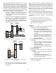
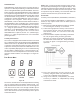
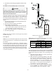
GAS SUPPLY PRESSURE MEASUREMENT
White-Rodgers Model 36J54 (Two-Stage)
Figure 62A
Inlet
Pressure
Boss
Low Fire
Regulator
Adjust
M
a
n
o
m
e
t
e
r
M
a
n
o
m
e
t
e
r
H
o
s
e
High Fire Regulator
Adjust
Regulator
Vent
Outlet
Pressure Boss
Open to
Atmosphere
O
n
/
O
f
f
S
w
i
t
c
h
H
i
g
h
F
i
r
e
C
o
i
l
T
e
r
m
i
n
a
l
(
H
I
)
C
o
a
x
i
a
l
C
o
i
l
T
e
r
m
i
n
a
l
(
M
)
Common
Terminal(C)
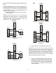
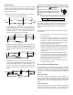
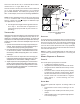
White-Rodgers Model 36J54 Connected to Manometer
Figure 62B
Natural Gas Minimum: 4.5" w.c. Maximum: 10.0" w.c.
Propane Gas Minimum: 11.0" w.c. Maximum: 13.0" w.c.
INLET GAS SUPPLY PRESSURE
CAUTION
T
O
PREVENT
UNRELIABLE
OPERATION
OR
EQUIPMENT
DAMAGE
,
THE
INLET
GAS
SUPPLY
PRESSURE
MUST
BE
AS
SPECIFIED
ON
THE
UNIT
RATING
PLATE
WITH
ALL
OTHER
HOUSEHOLD
GAS
FIRED
APPLIANCES
OPERATING
.
The line pressure supplied to the gas valve must be within the
range specified below. The supply pressure can be measured
at the gas valve inlet pressure tap or at a hose fitting in-
stalled in the gas piping drip leg. The supply pressure must
be measured with the burners operating. To measure the gas
supply pressure, use the following procedure.
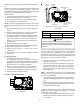
1. Turn OFF gas to furnace at the manual gas shutoff valve
external to the furnace.
2. Connect a calibrated water manometer (or appropriate
gas pressure gauge) at either the gas valve inlet
pressure tap or the gas piping drip leg. See White-
Rodgers 36J54 gas valve (Figure 43B) fto locate the
inlet pressure tap.
NOTE: If using the inlet pressure tap on the White-Rodgers
36J54 gas valve, then use the 36G/J Valve Pressure Check
Kit, Part No. 0151K00000S.
3. Turn ON the gas supply and operate the furnace and all
other gas consuming appliances on the same gas supply
line.
4. Measure furnace gas supply pressure with burners firing.
Supply pressure must be within the range specified in the
Inlet Gas Supply Pressure table.
If supply pressure differs from table, make the necessary ad-
justments to pressure regulator, gas piping size, etc., and/or
consult with local gas utility.
5. Turn OFF gas to furnace at the manual shutoff valve and
disconnect manometer. Reinstall plug before turning on
gas to furnace.