
Installation Guide


13
VENT/FLUE PIPE
The vent pipe outlet is sized to accept 2” pipe. Secure vent/
flue pipe directly into the furnace fitting with the appropri-
ate glue. Alternately, a small section of 2" pipe may be glued
in the furnace socket and a rubber coupling installed to allow
removal for future service. Combustion Air and Vent piping
should be routed in a manner to avoid contact with refriger-
ant lines, metering devices, condensate drain lines, etc. If
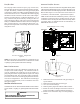
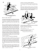
sary, clearances may be increased by creating an offset us-
ing two 45 degree elbows. This joint can be rotated on the
fitting to establish maximum clearance between refrigerant
lines, metering devices, and condensate drain lines, etc.
This joint is the equivalent of one 90 deg. elbow when consid-
ering elbow count.
45 DEGREE
LONG-SWEEP
ELBOWS
V
E
N
T
Increased Clearance Configuration
Figure 8
NOTE: For non-direct vent installations, a minimum of one
90° elbow should be installed on the combustion air intake
coupling to guard against inadvertent blockage.
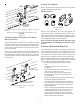
DIRECT VENT INSTALLATIONS
On upflow units secure the combustion air intake pipe di-
rectly to the air intake coupling. On counterflow units se-
cure the combustion air intake pipe to the air intake cou-
pling using the rubber coupling and worm gear hose clamps
provided with the unit. The counterflow rubber coupling al-
lows service removal of air intake piping internal to the fur-
nace blower compartment. The combustion air intake pipe
can also be secured directly to the counterflow unit air in-
take pipe coupling.
NON-DIRECT VENT I NSTALLATIONS
A minimum of one 90° elbow should be installed on the combus-
tion air intake “coupling” to guard against inadvertent block-
age.
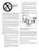
E
DGES
OF
SHEET
METAL
HOLES
MAY
BE
SHARP
. U
SE
GLOVES
AS
A
PRECAUTION
WHEN
REMOVING
HOLE
PLUGS
.
WARNING
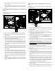
ALTERNATE VENT/FLUE LOCATION
The alternate vent/flue location is the large hole directly in line
with the induced draft blower outlet. To use the alternate vent/
flue location refer to the following steps and the “Alternate Vent/
Flue Location” figure. To use an alternate vent location on a
counterflow / horizontal model, a special kit is required.
NOTE: In the horizontal left installation position, a means of
condensate collection must be provided to keep vent pipe
condensate from entering the draft inducer housing. If the
vent drain elbow is eliminated from the installation, an
RF000142 kit must be used.
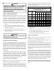
Insert flange. Cut 2 ½” long.
R 000142F
Figure 9
C
U
T
H
E
R
E
Vent/Flue Pipe Cuts
Figure 10
1. Remove the four screws from the vent pipe flange on
top the furnace.
2. Remove the internal elbow and vent pipe
3. Cut 2 1/2" from the flange .
4. Remove plastic plug in line with the inducer outlet
5. Install cut end of the flanged section and connect to
inducer with rubber coupling supplied with furnace.
6. Install screws removed in step 1 securing flange to
cabinet.