
Service Manual


INSTALLATION CONSIDERATIONS
23
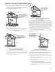
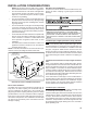
Installation Positions
*MVC96 models may be installed up flow or horizontally
with left or right side down. *CVC96 models may be installed
down flow or horizontally with left or right side down. Do not
install any furnace on its back.
Horizontal Installations
1. Horizontal installations require 5.5" under the furnace
to accommodate the drain trap.
2. Horizontal furnaces must be installed with ¾” slope from
back to front to permit condensate flow towards the
front of the furnace.
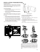
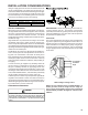
When installing a *MVC96 horizontally with the left side
down, there are two options for connecting the vent pipe to
the furnace.
1. Venting may be connected to the furnace vent pipe fit-
ting on the original top (now the end) of the furnace
2. The internal vent pipe and elbow may be removed from
the furnace to permit the vent to exit the top (original
side) of the furnace. If this option is used, an RF000142
Vent-Drain coupling must be used to keep condensate
from collecting in the inducer assembly.
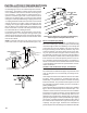
Refer to the following instructions and illustration.
Insert flange. Cut 2 ½” long.
R 000142F
C
U
T
H
E
R
E
Vent/Flue Pipe Cuts
1. Remove screws from vent flange.
2. Remove internal elbow and vent pipe.
3. Cut pipe 2 1/2” from flange.
4. Remove cabinet plug adjacent to inducer outlet and in-
stall an original cabinet vent hole.
5. Install RF000142 coupling on inducer outlet.
6. Install flanged vent section removed in step 2 & secure
with clamps.
7. Secure flange to cabinet using screws removed in step
1.
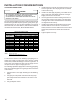
90% Furnace Recommended Installation Positions
NOTE: Alternate "vertical" piping connections can not be
used when an upflow 90% furnace is installed with supply
air discharging to the right or when a counterflow furnace is
installed with supply discharging to the left. In this case,
use the standard flue and combustion air piping connec-
tions