
Service Manual


SYSTEM OPERATION
68
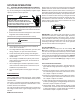
7. Locate the 3-circuit connector in the control/end bell. Using
an ohmmeter, check the resistance between each termi-
nal in the connector. If the resistance is 100kΩ or greater,
the control/end bell is functioning properly. Replace the
control/end bell if the resistance is lower than 100kΩ.
8. Reassemble motor and control/end bell in reverse of dis-
assembly. Replace blower assembly into the furnace.
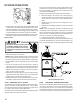
Motor Checks
HIGH VOLTAGE!
Disconnect ALL power before servicing
or installing. Multiple power sources
may be present. Failure to do so may
cause property damage, personal injury
or death.
1. Disconnect power to the furnace.
NOTE: Motor contains capacitors that can hold a charge
for several minutes after disconnecting power. Wait 5 min-
utes after removing power to allow capacitors to discharge.
2. Disassemble motor as described in steps 2 through 4
above.
3. Locate the 3-circuit harness from the motor. Using an
ohmmeter, measure the resistance between each motor
phase winding. The resistance levels should be equal.
Replace the motor if the resistance levels are unequal,
open circuited or short circuited.
4. Measure the resistance between each motor phase wind-
ing and the motor shell. Replace the motor if any phase
winding is short circuited to the motor shell.
5. Reassemble motor and control/end bell in reverse of dis-
assembly. Replace blower assembly into the furnace.
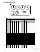
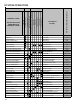
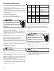
S-200 CHECKING DUCT STATIC
The maximum and minimum allowable external static pres-
sures are found in the specification section. These tables
also show the amount of air being delivered at a given static
by a given motor speed or pulley adjustment.
The furnace motor cannot deliver proper air quantities (CFM)
against statics other than those listed.
Too great of an external static pressure will result in insuffi-
cient air that can cause excessive temperature rise, result-
ing in limit tripping, etc. Whereas not enough static may
result in motor overloading.
To determine proper air movement, proceed as follows:
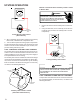
1. With clean filters in the furnace, use a draft gauge (in-
clined manometer) to measure the static pressure of the
return duct at the inlet of the furnace. (Negative Pres-
sure)
2. Measure the static pressure of the supply duct. (Posi-
tive Pressure)
3. Add the two (2) readings together for total external static
pressure.
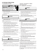
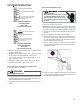
NOTE: Both readings may be taken simultaneously and
read directly on the manometer if so desired. If an air condi-
tioner coil or Electronic Air Cleaner is used in conjunction
with the furnace, the readings must also include theses com-
ponents, as shown in the following drawing.
4. Consult proper tables for the quantity of air.
If the total external static pressure exceeds the minimum or
maximum allowable statics, check for closed dampers, reg-
isters, undersized and/or oversized poorly laid out duct work.
Checking Static Pressure
S-201 CHECKING TEMPERATURE RISE
The more air (CFM) being delivered through a given furnace,
the less the rise will be; so the less air (CFM) being deliv-
ered, the greater the rise. The temperature rise should be
adjusted in accordance to a given furnace specifications and
its external static pressure. An incorrect temperature rise