
Service Manual


SYSTEM OPERATION
71
*
*
*
**
*
*
2
FLAME
ROLLOUT
SWITCHES
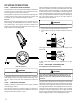
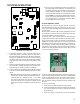
Flame Rollout Switch Location
(90% Upflow Furnace Shown, Counterflow Similar)
The control is designed to open should a flame roll out oc-
cur. An over firing condition or flame impingement on the
heat shield may also cause the control to open. If the rollout
control opens, the air circulation blower will run continuously.
L
INE VOLTAGE NOW PRESENT
WARNING
1. Remove the burner compartment door to gain access to
the rollout switch(es) mounted to burner bracket.
2. Reset the manual rollout switch.
3. Remove wires from rollout switch.
4. Using an ohmmeter, check for coninuity across the swtch.
5. if the switch will not close afer manually resetting, it must
be replaced.
If a roll out switch has tripped, it is important to find out why.
Possible causes could be flame impingement, orifice plate
out of position, burners with excessive cross-over slot di-
mension, over-firing, improper orifices, improper gas pres-
sure, air leaking from around the heat exchanger into the
burner compartment, air leaking through the heat exchanger
itself.
6. After check and/or replacement of rollout switch, rein-
stall burner compartment door and verify proper unit op-
eration.
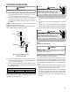
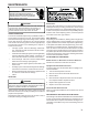
S-303 INDUCED DRAFT BLOWER Motor
WARNING
HIGH VOLTAGE
D
ISCONNECT ALL POWER BEFORE SERVICING OR
INSTALLING THIS UNIT.
MULTIPLE POWER SOURCES MAY
BE PRESENT.
FAILURE TO DO SO MAY CAUSE PROPERTY
DAMAGE, PERSONAL INJURY OR DEATH.
1. Remove burner compartment door to gain access to
the induced draft blower motor.
2. Disconnect the motor wire leads from its connection
point at the induced draft motor.
3. Using a ohmmeter, test for continuity between each of
the motor leads.
4. Touch one probe of the ohmmeter to the motor frame
(ground) and the other probe in turn to each lead.
If the windings do not test continuous or a reading is
obtained to ground, replace the motor.
5. If the windings have a continuity reading, reconnect
wires. Turn power on to the furnace and turn the ther-
mostat on in the heating mode. Check voltage for
115V at the induced draft motor terminals during the
trial for ignition. If you have 115V and the motor does
not run, replace the induced draft motor.
6. After completing check and/or replacement of induced
draft motor, reinstall burner compartment door.
7. Turn on electrical power and verify proper unit opera-
tion.
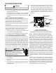
S-304 CHECKING GAS VALVE (Redundant)
A combination redundant operator type gas valve which pro-
vides all manual and automatic control functions required for
gas fired heating equipment is used.
The valve provides control of main burner gas flow, pressure
regulation, and 100 percent safety shut-off.
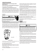
Two stage gas valves always require 24 volts between com-
mon and low fire (main coil) to open. The furnace front cover
pressure switch is wired in series with the low (main) sole-
noid of the gas valve. In the event of a non-functioning gas
valve, always check the front cover pressure switch. Also
see section S-307 on Checking Gas Pressure and section
S-310 on Checking Pressure Switches.
Low (Main)
Common
High
White-Rodgers 2-Stage Valve
WARNING
D
ISCONNECT
ALL
POWER BEFORE SERVICING