
Install Instructions


41
• Induced draft blower steps to low speed following
prepurge. Low stage pressure switch contacts are
closed.
• Igniter warm up begins upon Inducer draft blower
step to low speed and presence of closed low stage
pressure switch contacts.
• Gas valve opens at end of igniter warm up period,
delivering gas to burners and establishing flame.
• Integrated control module monitors flame presence.
Gas valve will remain open only if flame is detected.
• Based on the furnace internal control algorithms the
gas valve and induced draft blower may continue
operating on low stage or both will change to high
stage. After a power cycle, the first gas heat call
will result in high stage operation.
• Circulator blower is energized on heat speed
following the selected blower on delay and will begin
to ramp up. Electronic air cleaner terminal is
energized with circulator blower.
• Furnace is now operating on the specified stage
determined by the internal control algorithm.
• Furnace runs, integrated control module monitors
safety circuits continuously.
• If the internal algorithm changes the call from low
heat to high heat, the integrated control module
will immediately switch the induced draft blower,
gas valve, and circulator blower to their high stage
settings.
• If the internal algorithm changes the call from
high heat to low heat, the control will immediately
switch the induced draft blower and gas valve to
their low stage settings. The circulator blower
remains on high heating speed for 30 seconds
before switching to the low heat circulating speed.
• The W terminal thermostat contacts open, which
ends the call for heat.
• The gas valve closes, extinguishing the flame.
• Induced draft blower is de-energized following a 15
second post purge.
• Circulator blower continues running for the selected
heat off delay period. The blower speed during
this period depends on the last heat call provided by
the thermostat. If the last call for heat was a call
for low heat, the air circulator motor will run on low
heat speed for the duration of the heat off delay
period. If the last call for heat was a call for high
heat, the air circulating motor will run on low heat
speed for the duration of the heat off delay period.
If the last call for heat was a call for high heat, the
air cirulating motor will run on the high heating speed
for thirty (30) seconds and then switch to the low
heating spped for the reminder of the heat off delay
period.
• Circulator blower and electronic air cleaner terminal
are de-energized.
• Circulator blower shuts off after the heat off delay
period expires.
• Furnace awaits next call from thermostat.
O
PERATIONAL
C
HECKS
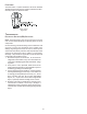
The burner flames should be inspected with the burner com-
partment door installed. Flames should be stable, quiet, soft,
and blue (dust may cause orange tips but they must not be
yellow). Flames should extend directly outward from the burn-
ers without curling, floating, or lifting off. Flames must not
impinge on the sides of the heat exchanger firing tubes.
S
AFETY
C
IRCUIT
D
ESCRIPTION
A number of safety circuits are employed to ensure safe and
proper furnace operation. These circuits serve to control any
potential safety hazards and serve as inputs in the monitoring
and diagnosis of abnormal function. These circuits are continu-
ously monitored during furnace operation by the integrated con-
trol module.
INTEGRATED CONTROL MODULE
The integrated control module is an electronic device which,
if a potential safety concern is detected, will take the neces-
sary precautions and provide diagnostic information through
an LED.
PRIMARY LIMIT
The primary limit control is located on the partition panel and
monitors heat exchanger compartment temperatures. It is a
normally-closed (electrically), automatic reset, temperature-
activated sensor. The limit guards against overheating as a
result of insufficient conditioned air passing over the heat
exchanger.
AUXILIARY LIMIT
The auxiliary limit controls are located on or near the circulator
blower and monitors blower compartment temperatures. They
are a normally-closed (electrically), manual-reset sensors. These
limits guard against overheating as a result of insufficient condi-
tioned air passing over the heat exchanger.
ROLLOUT LIMIT
The rollout limit controls are mounted on the burner/mani-
fold assembly and monitor the burner flame. They are nor-
mally-closed (electrically), manual-reset sensors. These lim-
its guard against burner flames not being properly drawn into
the heat exchanger.Pressure Switches.
PRESSURE SWITCHES
The pressure switches are normally-open (closed during op-
eration) negative air pressure-activated switches. They moni-
tor the airflow (combustion air and flue products) through the
heat exchanger via pressure taps located on the induced draft
blower and the coil front cover. These switches guard against
insufficient airflow (combustion air and flue products) through
the heat exchanger and/or blocked condensate drain conditions.