
Service Manual


INSTALLATION CONSIDERATIONS
32
WARNING
I
F THE INFORMATION IN THESE INSTRUCTIONS IS NOT FOLLOWED EXACTLY, A
FIRE OR EXPLOSION MAY RESULT CAUSING PROPERTY DAMAGE, PERSONAL
INJURY OR LOSS OF LIFE.
–
D
O NOT STORE OR USE GASOLINE OR OTHER FLAMMABLE VAPORS AND
LIQUIDS IN THE VICINITY OF THIS OR ANY OTHER APPLIANCE.
–
WHAT
TO
DO
IF
YOU
SMELL
GAS
:
•
D
O NOT TRY TO LIGHT ANY APPLIANCE.
•
D
O NOT TOUCH ANY ELECTRICAL SWITCH; DO NOT USE ANY
PHONE IN YOUR BUILDING.
•
I
MMEDIATELY CALL YOUR GAS SUPPLIER FROM A NEIGHBOR’S
PHONE.
F
OLLOW THE GAS SUPPLIER’S INSTRUCTIONS.
•
I
F YOU CANNOT REACH YOUR GAS SUPPLIER, CALL THE FIRE
DEPARTMENT.
–
I
NSTALLATION AND SERVICE MUST BE PERFORMED BY A QUALIFIED INSTALLER,
SERVICE AGENCY OR THE GAS SUPPLIER.
3/8" 1/2" 5/8" 3/4" 7/8" 1/2" 3/4"
10 730 1,700 3,200 5,300 8,300 3,200 7,500
20 500 1,100 220 3,700 5 ,800 2,200 4,200
30 400 920 2,000 2,900 4,700 1,800 4,000
40 370 850 1,700 2,700 4,100 1,600 3,700
50 330 770 1,500 2,400 3,700 1,500 3,400
60 300 700 1,300 2,200 3,300 1,300 3,100
80 260 610 1,200 1,900 2,900 1,200 2,600
100 220 540 1,000 1,700 2 ,600 1,000 2,300
125 200 490 900 1,400 2,300 900 2,100
150 190 430 830 1,300 2,100 830 1,900
175 170 400 780 1,200 1,900 770 1,700
200 160 380 730 1,100 1,800 720 1,500
Pipe or
Tubing
Length
Feet
Tubing Size, O.D . Type L
Nominal Pipe Size
Schedule 40
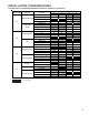
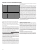
Sizing Between First and Second Stage Regulator*
Maximum Propane Capacities listed are based on 2 psig pressure drop at 10 psig setting.
Capacities in 1,000 BTU/hour.
To convert to capacities at 15 psig settings - multiply by 1.130
To convert to capacities at 5 psig settings - multiply by 0.879
3/8" 1/2" 5/8" 3/4" 7/8" 1/2" 3/4" 1" 1-1/4" 1-1/2"
10 39 92 199 329 501 275 5 67 1,07 1 2,205 3,307
20 26 62 131 216 346 189 3 93 732 1,496 2,299
30 21 50 107 181 277 152 3 15 590 1,212 1,858
40 19 41 90 145 233 129 2 67 504 1,039 1,559
50 18 37 79 131 198 114 2 37 448 913 1,417
60 16 35 72 1,211 187 103 2 17 40 9 834 1,275
80 13 29 62 104 155 89 185 34 6 724 1,066
100 11 26 55 90 138 78 162 30 7 630 976
125 10 24 48 81 122 69 146 27 5 567 866
150 9 21 43 72 109 63 1 32 25 2 511 787
200 8 19 39 66 100 54 1 12 20 9 439 665
250 8 17 36 60 93 48 1 00 185 390 590
Tubing Size, O.D. Type L
Nominal Pipe Size
Schedule 40
Pipe or
Tubi ng
Length
Feet
*Data in accordance with NFPA pamphlet No. 54
Sizing Between Second or Second Stage Regulator & Appliance*
Maximum Propane Capacities listed are based on 1/2" W.C. pressure drop at 11" W.C. setting.
Capacities in 1,000 BTU/hour.
Propane Gas Piping Charts
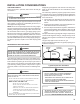
When installing a propane storage tank, the contractor must
consider proper tank sizing, safety, efficiency, ground char-
acteristics and aesthetics. For a residential customer, the
size may range from 100-1,000 gallons, depending on house-
hold use. Typically, a 500 gallon tank is ample for an aver-
age four-bedroom home. However, it is best to consult your
local propane supplier to ensure the proper sizing for pro-
pane storage requirements. Determining the correct tank
size for each household is a function of demand, economy,
efficiency and convenience. It is a process that requires
cooperation between the propane supplier and customer.
ELECTRICAL CONNECTIONS
WARNING
TO AVOID THE RISK OF ELECTRICAL SHOCK, WIRING TO THE UNIT MUST BE
PROPERLY POLARIZED AND GROUNDED.
WARNING
HIGH
VOLTAGE
D
ISCONNECT ALL POWER BEFORE SERVICING OR
INSTALLING THIS UNIT.
MULTIPLE POWER SOURCES MAY
BE PRESENT.
FAILURE TO DO SO MAY CAUSE PROPERTY
DAMAGE, PERSONAL INJURY OR DEATH.
CAUTION
L
ABEL ALL WIRES PRIOR TO DISCONNECTION WHEN SERVICING CONTROLS.
WIRING ERRORS CAN COUSE IMPROPER AND DANGEROUS OPERATION.
VERIFY PROPER OPERATION AFTER SERVICING.
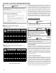
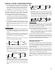
WIRING HARNESS
The wiring harness is an integral part of this furnace. Field
alteration to comply with electrical codes should not be
required. Wires are color coded for identification purposes.
Refer to the wiring diagram for wire routings. If any of the
original wire as supplied with the furnace must be replaced,
it must be replaced with wiring material having a tempera-
ture rating of at least 105° C. Any replacement wiring must
be copper conductor.
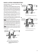
115 VOLT LINE CONNECTIONS
Before proceeding with electrical connections, ensure that
the supply voltage, frequency, and phase correspond to
that specified on the unit rating plate. Power supply to the
furnace must be N.E.C. Class 1, and must comply with all
applicable codes. The furnace must be electrically grounded
in accordance with local codes or, in their absence, with
the latest edition of The National Electric Code, ANSI NFPA
70 and/or The Canadian Electric Code CSA C22.1.