
Service Manual


INSTALLATION CONSIDERATIONS
35
Thermostat Wiring - Two-Stage Variable Speed
ComfortNet™ Furnaces
As a two-stage non-communicating furnace, the furnace
integrated control module provides terminals for both “W1”
and “W2”, and “Y1” and “Y2” thermostat connections. This
allows the furnace to support the following system applica-
tions: ‘Two-Stage Heating Only’, ‘Two-Stage Heating with
Single Stage Cooling’, and ‘Two-Stage Heating with Two-
Stage Cooling’. Refer to the following figures for proper
connections to the integrated control module.
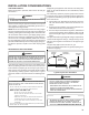
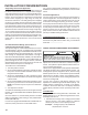
Low voltage connections can be made through either the
right or left side panel. Thermostat wiring entrance holes
are located in the blower compartment. The following figure
shows connections for a “heat/cool system”.
This furnace is equipped with a 40 VA transformer to facili-
tate use with most cooling equipment. Consult the wiring
diagram, located on the blower compartment door, for fur-
ther details of 115 Volt and 24 Volt wiring.
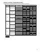
NOTE: For single stage cooling applications, a jumper may
be required between Y1 and Y2 at the furnace control in
order to achieve the desired single stage cooling airflow.
Consult the blower performance tables to determine if the
required single stage cooling airflow can be delivered at low
stage (Y1 input) or high stage (Y2 input). Additionally, use
of ramping profile features require a jumper between Y1 and
O when used with a straight cooling unit.
NOTE: Thermostat “R” required if outdoor unit is equipped
with a Comfort Alert™ module or if the out door unit is a
part of the ComfortNet family of equipment AND is wired as
a legacy system.
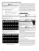
Y
R
R
Y C
NEU
Furnace Integrated
Control Module
Remote
Condensing Unit
(Single-Stage Cooling)
Dehumidistat
[Optional]
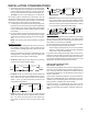
To apply a single-stage Heating Thermostat,
the thermostat selector switch on the
Integrated Control Module be set on
single-stage.
must
NOTE:
Single Stage Heating with Single Stage Cooling
Thermostat
Single Stage Heating with
Single Stage Cooling
In a Non-Dual Fuel
Application, Place Jumper
Between Y1 and O For
Proper Dehumidification
Operation and Proper
Ramping Profile Operation
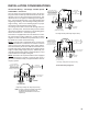
Y
Two-Stage Heating with Single-Stage Cooling
R
R
Y C
Furnace Integrated
Control Module
Thermostat
Two-Stage Heating
with
Single-Stage Cooling
Remote
Condensing Unit
(Single-Stage Cooling)
Dehumidistat
[Optional]
NEU
In a Non-Dual Fuel
Application, Place Jumper
Between Y1 and O For
Proper Dehumidification
Operation and Proper
Ramping Profile Operation
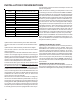
Two-Stage Heating with Two-Stage Cooling
W1 W2
Y2
Furnace Integrated
Control Module
Thermostat
Two-Stage Heating
with
Two-Stage Cooling
()
Remote
Condensing Unit
(Two-Stage Cooling)
Dehumidistat
[Optional]
Y2
Y2
W2
W1
NEU
In a Non-Dual Fuel
Application, Place Jumper
Between Y1 and O For
Proper Dehumidification
Operation and Proper
Ramping Profile Operation
Thermostat Wiring Diagrams