
Service Manual


SYSTEM OPERATION
54
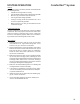
ComfortNet™ System
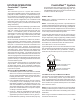
If your communicating thermostat kit does not include a
transformer, an accessory kit is available separately by
ordering part TFK01.
1
2R
C
12RC
12
RC
CTK0***
Thermostat
ComfortNet Compatible
Furnace Integrated
Control Module
ComfortNet Compatible
AC/HP Integrated
Control Module
40VA Transformer
208/230 VAC
24 VAC
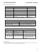
SYSTEM WIRING USING TWO-WIRES BETWEEN FURNACE AND
FOUR-WIRES BETWEEN F URNACE AND T HERMOSTAT
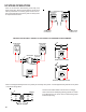
COMFORTNET F URNACE WITH N ON-COMFORTNET A/C
S
INGLE STAGE A IR C ONDITIONER
Four wires are required between the furnace and thermo-
stat. Two wires are required between the furnace control
and single stage air conditioner. For this system configura-
tion, the “Y1” terminal on the integrated furnace control be-
comes an output rather than an input.
1
2R
C
12RC
C Y
ComfortNet
Compatible
Furnace Integrated
Control Module
CTK0***
Thermostat
Non-ComfortNet Compatible
Single Stage AC
G
W1 W2 Y1 Y2
O
SYSTEM WIRING BETWEEN F URNACE AND N ON-COMFORTNET
COMPATIBLE SINGLE STAGE AIR CONDITIONER
COMFORTNET S YSTEM ADVANCED F EATURES
The ComfortNet system permits access to additional sys-
tem information, advanced setup features, and advanced di-
agnostic/troubleshooting features. These advanced features
are organized into a menu structure.
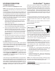
NOTE: PCBKF105 IFC has the added feature of 24 VAC
input to G terminal when using a communicating thermostat.
ERV/HRV and other assessories can send a signal to the G
terminal and energize the continuous fan. The continuous
fan speed can be adjusted on switch bank S5, dip switch 3
& 4. The 24 vac source must originate from the R terminal of
furnace.
W1 W2 Y1 Y2 O DEHUM
Furnace Integrated
Control Module
RC
G
CTK0* Thermostat
4-Pin (X2), 7 Pin, or 9 Pin Connector
24 vac "G" input to Furnace
Integrated Control module From
ERV / HRV or Similar Devices
1
1
2RC
2