
Service Manual


SYSTEM OPERATION
65
S-4 CHECKING TRANSFORMER AND Control CIRCUIT
A step-down transformer 120 volt primary to 24 volt second-
ary, 40 VA (Heating and Cooling Models) supplies ample
capacity of power for either operation.
WARNING
HIGH
VOLTAGE
D
ISCONNECT ALL POWER BEFORE SERVICING OR
CHANGING ANY ELECTRICAL WIRING.
MULTIPLE POWER
SOURCES MAY BE PRESENT.
FAILURE TO DO SO MAY CAUSE
PROPERTY DAMAGE, PERSONAL INJURY OR DEATH.
1. Remove blower compartment door to gain access to the
thermostat low voltage wires located at the furnace inte-
grated control module.
2. Remove the thermostat low voltage wires at the furnace
integrated control module terminals.
With Power On (and Door Interlock Switch closed):
LINE VOLTAGE NOW PRESENT
WARNING
3. Use a voltmeter, check voltage across terminals R
and C. Must read 24 VAC.
4. No voltage indicates faulty transformer, open fuse, bad
wiring, bad splice, or open door interlock switch.
5. Check transformer primary voltage at incoming line
voltage connections, fuse, splices, and blower door in-
terlock switch.
6. If line voltage is available to the primary side of trans-
former and not at secondary side, the transformer is
inoperative. Replace.
7. After completing check and/or replacement of trans-
former and check and/or repair of control circuit, rein-
stall blower compartment door.
8. Turn on electrical power and verify proper unit opera-
tion.
4-Wire ECM Motors
Description
These models utilize an Nidec US motors, 4-wire variable
speed ECM blower motor. The ECM blower motor provides
constant CFM.
The motor is a serially communicating variable speed mo-
tor. Only four wires are required to control the motor: +Vdc,
Common, Receive, and Transmit.
The +Vdc and Common wires provide power to the motor's
low voltage control circuits. Typical supply voltage is 9-15
volts DC.
ECM Control Connections
ECM control connections are made through the integrated
ignition control. No other control connections are needed.
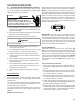
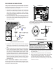
NOTE: An inductor (Factor Power Choke Correction) is re-
quired when powering the 3/4 and 1 horsepower motors with
115 volts (inductor pictured below). The operation of this in-
ductor is to reduce the line current by storing the electrical
energy in a magnetic field, such that the voltage AC wave-
form leads the current AC waveform. In other words, the
inductor reduces line current which extends the life of the
3/4 and 1 horsepower motors.
IMPORTANT: If the inductor fails, there will be no motor
operation since this is the "LINE" power supply, black wire,
from the integrated ignition control to the motor. To deter-
mine if the inductor is at fault, you can bypass by the induc-
tor by disconnecting the black wire from the inductor and
connecting it directly to the motor. If the motor operates
then the inductor will need to be replaced.
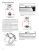
Checking ECM Motors
ECMmotors connect directly to the AC Line Voltage. DO
NOT insert contactors in series with the ECM Motor AC
Line. The control is powered continuously to insure reliable
start-up. The connector plug is polarized, verify and reverify
correct connector orientation before applying power. DO NOT
force plug into motor and make sure power is off before in-
serting power connector. DO NOT apply voltage to termi-
nals 1 or 2.
General Checks/Considerations
1. Check power supply to the furnace. Ensure power sup-
ply is within the range specified on rating plate. See sec-
tion S-1.
2. Check motor power harness. Ensure wires are continu-
ous and make good contact when seated in the connec-
tors. Repair or replace as needed.
3. Check motor control harness. Ensure wires are continu-
ous and make good contact when seated in the connec-
tors. Repair or replace as needed.
4. Check thermostat and thermostat wiring. Ensure ther-
mostat is providing proper cooling/heating/continuous fan
demands. Repair or replace as needed.
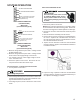
5. Check blower wheel. Confirm wheel is properly seated
on motor shaft. Set screw must be on shaft flat and torqued
to 165 in-lbs minimum. Confirm wheel has no broken or
loose blades. Repair or replace as needed.