
Service Manual


SYSTEM OPERATION
69
may result in condensing in or overheating of the heat ex-
changer. An airflow and temperature rise table is provided
in the blower performance specification section. Determine
and adjust temperature rise as follows:
1. Operate furnace with burners firing for approximately ten
minutes. Check BTU input to furnace - do not exceed
input rating stamped on rating plate. Ensure all regis-
ters are open and all duct dampers are in their final (fully
or partially open) position.
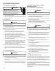
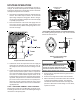
2. Place thermometers in the return and supply ducts as
close to the furnace as possible. Thermometers must
not be influenced by radiant heat by being able to “see”
the heat exchanger.
SUPPLY
AIR
RETURN
AIR
Temperature Rise Measurement
3. Subtract the return air temperature from the supply air
temperature to determine the air temperature rise. Al-
low adequate time for thermometer readings to stabi-
lize.
4. Adjust temperature rise by adjusting the circulator blower
speed. Increase blower speed to reduce temperature
rise. Decrease blower speed to increase temperature
rise. Refer to Circulator Blower Speed section in the
Product Design section of this manual for speed chang-
ing details. Temperature rise is related to the BTUH out-
put of the furnace and the amount of air (CFM) circu-
lated over the heat exchanger. Measure motor current
draw to determine that the motor is not overloaded dur-
ing adjustments.
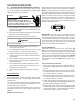
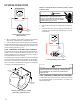
S-300 CHECKING PRIMARY LIMIT CONTROL
Primary limit controls are nonadjustable, automatic reset,
bi-metal type limit control. Refer to the following drawing for
the location of the primary limit.
*
*
*
**
*
*
2
PRIMARY LIMIT
CONTROL
Primary Limit Control Location
(90% Upflow Furnace Shown, Counterflow Similar)
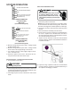
The following drawing illustrates the style of limit switches
used on the 90% furnaces.
ENCLOSED DISK
FRONT VIEW SIDE VIEW
Primary Limit Control Style
(90% Furnaces)
WARNING
HIGH
VOLTAGE
D
ISCONNECT ALL POWER BEFORE SERVICING OR
CHANGING ANY ELECTRICAL WIRING.
MULTIPLE POWER
SOURCES MAY BE PRESENT.
FAILURE TO DO SO MAY CAUSE
PROPERTY DAMAGE, PERSONAL INJURY OR DEATH.
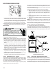
1. Remove burner compartment door to gain access to
the primary limit.
2. Remove low voltage wires at limit control terminals.
3. With an ohmmeter, test between these two terminals
as shown in the following drawing. The ohmmeter
should read continuous unless heat exchanger tem-
perature is above limit control setting. If not as above,
replace the control.