INSTALLATION INSTRUCTIONS FOR *MVM97 & *CVM97 MODULATING GAS FURNACE (Type FSP CATEGORY IV Direct or Non Direct Vent Air Furnace) These furnaces comply with requirements embodied in the American National Standard / National Standard of Canada ANSI Z21.47·CSA-2.3 Gas Fired Central Furnaces. Installer: Affix all manuals adjacent to the unit. As a professional installer you have an obligation to know the product better than the customer. This includes all safety precautions and related items.
TABLE OF CONTENTS DRAIN EXITING RIGHT SIDE ...................................... 26 UPFLOW MODEL INSTALLED HORIZONTALLY WITH LEFT SIDE DOWN - ALTERNATE ...................... 26 COUNTERFLOW MODEL INSTALLED VERTICALLY .................... 26 DRAIN EXITING LEFT SIDE ....................................... 26 COUNTERFLOW MODEL INSTALLED HORIZONTALLY WITH RIGHT SIDE DOWN .................................. 27 COUNTERFLOW MODEL INSTALLED HORIZONTALLY WITH LEFT SIDE DOWN ...................................
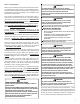
SAFETY CONSIDERATIONS WARNING Adhere to the following warnings and cautions when installing, adjusting, altering, servicing, or operating the furnace. To ensure proper installation and operation, thoroughly read this manual for specifics pertaining to the installation and application of this product. This furnace is manufactured for use with natural gas. It may be field converted to operate on L.P. gas by using the appropriate L.P.
RISQUE D'EMPOISONNEMENT AU MONOXYDE DE CARBONE Advertencia especial para la instalación de calentadores ó manejadoras de aire en áreas cerradas como estacionamientos ó cuartos de servicio. Las emisiones de monóxido de carbono pueden circular a través del aparato cuando se opera en cualquier modo. CO can cause serious illness including permanent brain damage or death.
1. Disconnect all power to the furnace. Do not touch the integrated control module or any wire connected to the control prior to discharging your body’s electrostatic charge to ground. 2. Firmly touch a clean, unpainted, metal surface of the furnaces near the control. Any tools held in a person’s hand during grounding will be discharged. 3. Service integrated control module or connecting wiring following the discharge process in step 2. Use caution not to recharge your body with static electricity; (i.e.
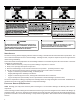
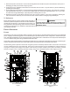
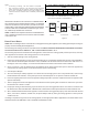
1 2 3 4 5 6 7 8 9 10 11 12 13 14 15 16 Gas Valve Gas Line Entrance (Alternate) Pressure Switch(es) Gas Manifold Combustion Air Intake Connection Hot Surface Igniter Rollout Limit Burners 17 18 19 20 21 22 23 24 Flame Sensor Flue Pipe Connection Flue Pipe Primary Limit Gas Line Entrance Flue Pipe Connection (Alternate) NK Rubber Elbow Variable-Speed Induced Draft Blower 25 26 27 28 29 30 31 32 Electrical Connection Inlets (Alternate) Coil Front Cover Pressure Tap Coil Front Cover Drain Port Drain Line P
• All furnace operating conditions (including ignition, input rate, temperature rise and venting) are verified according to these installation instructions. NOTE: The Commonwealth of Massachusetts requires that the following additional requirements must also be met: • Gas furnaces must be installed by a licensed plumber or gas fitter. • A T-handle gas cock must be used. • If the unit is to be installed in an attic, the passageway to and the service area around the unit must have flooring.
• • • • • • • • • • • Ensure upflow or horizontal furnaces are not installed directly on carpeting, or any other combustible material. The only combustible material allowed is wood. A special accessory subbase must be used for upright counterflow unit installations over any combustible material (including wood). Refer to subbase instructions for installation details.
NOTES: • For servicing or cleaning, a 24” front clearance is required. • Unit connections (electrical, flue and drain) may necessitate greater clearances than the minimum clearances listed above. • In all cases, accessibility clearance must take precedence over clearances from the enclosure where accessibility clearances are greater.
THERMOSTAT LOCATION The thermostat should be placed approximately five feet from the floor on a vibration-free, inside wall in an area having good air circulation. Do not install the thermostat where it may be influenced by any of the following: • Drafts, or dead spots behind doors, in corners, or under cabinets. • Hot or cold air from registers. • Radiant heat from the sun. • Light fixtures or other appliances. • Radiant heat from a fireplace. • Concealed hot or cold water pipes, or chimneys.
9.3.2 Indoor Combustion Air. The required volume of indoor air shall be determined in accordance with the method in 9.3.2.1 or 9.3.2.2 except that where the air infiltration rate is known to be less than 0.40 ACH, the method in 9.3.2.2 shall be used. The total required volume shall be the sum of the required volume calculated for all appliances located within the space.
(1)*Where directly communicating with the outdoors or where communicating to the outdoors through vertical ducts, each opening shall have a minimum free area of 1 in.2/4000 Btu/hr (550 min2/kW) of total input rating of all appliances in the enclosure. [See Figure A.9.3.3.1(1)(a) and Figure A.9.3.3.1(1)(b).] Figure A.9.3.3.1(1)(a) All Combustion Air From Outdoors Inlet Air from Ventilated Crawl Space and Outlet Air to Ventilated Attic. Figure A.9.3.3.
9.3.4 Combination Indoor and Outdoor Combustion Air. The use of a combination of indoor and outdoor combustion air shall be in accordance with (1) through (3) (see example calculation in Annex J]: (1) Indoor Openings: Where used, openings connecting the interior spaces shall comply with 9.3.2.3. (2) Outdoor Opening(s) Location. Outdoor opening(s) shall be located in accordance with 9.3.3. (3) Outdoor Opening(s) Size.
INSTALLATION POSITIONS A/GMVM97 models may be installed upflow or horizontally with left or right side down. A/GCVM97 models may be installed downflow or horizontally with left or right side down. Do not install this furnace on its back. For upright upflow furnaces, return air ductwork may be attached to the side panel(s) and/ or basepan. For horizontal upflow furnaces, return air ductwork must be attached to the basepan.
FRONT COVER PRESSURE SWITCH TUBE LOCATION When an upflow model is installed horizontally with left side down or a counterflow model is installed horizontally with right side down, the front cover pressure switch tube must be re-located to the lower port of the collector box cover. 1. Remove tube from front cover pressure switch and collector box cover. 2. Remove rubber plug from bottom collector box port and install on top collector box port. 3. Locate 24” x 1/4” tube in parts bag. 4.
VENT/FLUE PIPE & COMBUSTION AIR PIPE A condensing gas furnace achieves its high level of efficiency by extracting almost all of the heat from the products of combustion and cooling them to the point where condensation takes place. Because of the relatively low flue gas temperature and water condensation requirements, PVC or ABS pipe is used as venting material.
PROPER VENT/FLUE AND COMBUSTION AIR PIPING PRACTICES Adhere to these instructions to ensure safe and proper furnace performance. The length, diameter, and number of elbows of the vent/flue pipe and combustion air pipe (when applicable) affects the performance of the furnace and must be carefully sized. All piping must be installed in accordance with local codes and these instructions.
V X v DIRECT VENT TERMINAL CLEARANCES 1 Canadian Installations U.S. Installations Canadian Installations 2 A= Clearance above grade, veranda, porch, deck or balcony. (See 1.24.6-i(9)b.) 12 in. (30 cm) 12 in. (30 cm) B= Clearance to window or door that may be opened. 6 in. (15 cm) for appliances 10,000 Btuh (3 kW), 12 in. (30 cm) for appliances > 10,000 Btuh (3 kW) and 100,000 Btuh (30 kW), 36 in. (91 cm) for appliances > 100,000 Btuh (30 kW). 6 in.
SPECIAL VENTING REQUIREMENTS FOR INSTALLATIONS IN CANADA All installations in Canada must conform to the requirements of CAN/CSA B149.1 code. All vent system components, including primer and cement, must be listed to ULC S636. The certified pipe and fittings should be clearly marked with the ULC standard “S636”. The primer and cement used must be of the same manufacturer as the vent system. For Royal Pipe System 636; use GVS-65 Primer (Purple) and GVS-65 PVC Solvent Cement.
ALTERNATE VENT/FLUE LOCATION Insert flange. Cut 2 ½” long. The alternate vent/flue location is the large hole directly in line with the induced draft blower outlet. To use the alternate vent/flue location on an upflow / horizontal model, refer to the following steps and the “Alternate Vent/Flue Location” figure. To use an alternate vent location on a counterflow / horizontal model, a special kit is required.
air opening can be used. A locating dimple is located on the right side of the furnace cabinet. The locating dimple is 1 7/8" measured from the front edge of the cabinet in line with the knock out. To use the alternate combustion air location: 1. 2. 3. 4. 5. Remove screws and combustion air flange from cabinet. Insert cabinet plug in unused combustion air hole. Drill a pilot hole at the cabinet dimple (size dictated by knockout tool used).
12" MIN. VENT/FLUE TEE (OPTIONAL) or 45° ELBOW TURNED DOWN or 90° ELBOW TURNED DOWN 12" MIN. ABOVE HIGHEST ANTICIPATED SNOW LEVEL Horizontal Termination (Single Pipe) Above Highest Anticipated Snow Level Figure 15 VENT/FLUE & COMBUSTION AIR PIPE LENGTHS & DIAMETERS If there is a difference between the vent and combustion air pipes, count the pipe with the most fittings. Elbows and/or tees used in the terminations must be included when determining the number of elbows in the piping systems.
VENT/INTAKE TERMINATIONS FOR INSTALLATION OF MULTIPLE DIRECT VENT FURNACES If more than one direct vent furnace is to be installed vertically through a common roof top, maintain the same minimum clearances between the exhaust vent and air intake terminations of adjacent units as with the exhaust vent and air intake terminations of a single unit.
FIELD SUPPLIED DRAIN Drain the furnace and air conditioning coil if applicable, in compliance with code requirements. In horizontal or counterflow installations, a field installed rubber coupling will allow the drain trap to be removed for cleaning. The drain trap must be primed before initial furnace start up. When an air conditioning coil drain is connected to the field supplied furnace drain, it must be vented.
5. Refer to Field Supplied Drain section for instructions on field supplied / installed drain on outlet of furnace trap. UPFLOW MODEL INSTALLED HORIZONTALLY DOWN WITH RIGHT SIDE Minimum 5 3/8" clearance is required for the drain trap beneath the furnace. 1. Remove the clamps from both ends of the drain hoses. 2. Remove the two screws holding the drain trap to the blower deck. 3. Remove the trap and two hoses from the blower deck 4.
UPFLOW MODEL INSTALLED HORIZONTALLY WITH LEFT SIDE DOWN - ALTERNATE Insert flange. Cut 2 ½” long. RF000142 1. Install radius end of hose #5 on RF000142 coupling and secure with red clamp. 2. Insert coupling in hose #5. 3. Locate another hose #5 and cut 3” from the non-grommet end. Discard the section without the grommet. 4. Insert the cut end of tube #5 through the lower cabinet drain hole. 5. Insert 100 degree elbow in the cut end of hose #5. 6. Locate hose #6.
COUNTERFLOW MODEL INSTALLED HORIZONTALLY SIDE DOWN WITH RIGHT Minimum 5 3/8" clearance is required for the drain trap beneath the furnace. *Also see Front Cover Pressure Switch Tube Location on page 15. 1. Remove hose clamps and hoses from trap. 2. Remove trap. 3. (Draining the Collector Box) From outside the cabinet, insert the non-grommet end hose #8 into the back drain hole. 4. Secure to collector box drain port using a silver clamp. Drain Port 5.
ELECTRICAL CONNECTIONS WIRING HARNESS WARNING HIGH VOLTAGE ! The wiring harness is an integral part of this furnace. Wires are color coded for identification purposes. Refer to the wiring diagram for wire routings. If any of the original wire as supplied with the furnace must be replaced, it must be replaced with wiring material having a temperature rating of at least 105° C. Any replacement wiring must be a copper conductor.
To ensure proper unit grounding, an earth ground wire must be connected between the furnace ground screw located inside the furnace junction box and the electrical service panel. NOTE: Do not use gas piping as an electrical ground. To confirm proper unit grounding, turn off the electrical power and perform the following check. 1. Measure resistance between the neutral (white) connection and one of the burners. 2. Resistance should measure 10 ohms or less.
THERMOSTAT IMPORTANT NOTE R TO USE A SINGLE -STAGE HEAT THERMOSTAT , DIP SWITCH #13 ON THE FURNACE CONTROL BOARD MUST BE SET TO THE OFF POSITION . Furnace Integrated Control Module R THERMOSTAT R NEU Y C Dehumidistat [Optional] Remote Condensing Unit (Single-Stage Cooling) Thermostat - Single-Stage Heatingwith Single-Stage Cooling Figure 31 Field installed jumper to enable cooling ramping profile when using a straight cooling unit.
FOSSIL FUEL APPLICATIONS WARNING This furnace can be used in conjunction with a heat pump in a fossil fuel application. A fossil fuel application refers to a combined gas furnace and heat pump installation which uses an outdoor temperature sensor to determine the most cost efficient means of heating (heat pump or gas furnace). HIGH VOLTAGE ! TO AVOID PERSONAL INJURY OR DEATH DUE TO ELECTRICAL SHOCK, DISCONNECT ELECTRICAL POWER BEFORE SERVICING OR CHANGING ANY ELECTRICAL WIRING.
Inlet gas supply pressures must be maintained within the ranges specified in the following table. The supply pressure must be constant and available with all other household gas fired appliances operating. The minimum gas supply pressure must be maintained to prevent unreliable ignition. The maximum must not be exceeded to prevent unit overfiring. Natural Gas Propane Gas Inlet Gas Supply Pressure Minimum: 4.5" w.c. Maximum: 10.0" w.c. Minimum: 11.0" w.c. Maximum: 13.0" w.c.
• Install a drip leg to trap dirt and moisture before it can enter the gas valve. The drip leg must be a minimum of three inches • long. A line pressure test port is provided on the gas valve. If desired, install a 1/8" NPT pipe plug fitting, accessible for test gage connection, immediately upstream of the gas supply connection to the furnace. • Always use a back-up wrench when making the connection to the gas valve to keep it from turning.
Manual Shut Off Valve (upstream from ground joint pipe union) Alternate Union Location Grommet in Standard Gas Line Hole Manual Shut Off Valve (upstream from ground joint pipe union) Drip Leg Plug in Alternate Gas Line Hole Burners Manifold Gas Valve Plug in Main Gas Line Hole Drain Trap When gas line is in the alternate location, swap the position of the plug and grommet.
PROPANE GAS TANKS AND PIPING WARNING A gas detecting warning system is the only reliable way to detect a propane gas leak. Rust can reduce the level of odorant in propane gas. Do not rely on your sense of smell. Contact a local propane gas supplier about installing a gas detecting warning system. If the presence of gas is suspected, follow the instructions listed in the Safety Precautions section of this manual.
CIRCULATING AIR & FILTERS DUCT WORK - AIR FLOW Duct systems and register sizes must be properly designed for the CFM and external static pressure rating of the furnace. Design the ductwork in accordance with the recommended methods of “Air Conditioning Contractors of America” Manual D. WARNING NEVER ALLOW THE PRODUCTS OF COMBUSTION, INCLUDING CARBON MONOXIDE, TO ENTER THE RETURN DUCT WORK OR CIRCULATION AIR SUPPLY.
BOTTOM RETURN AIR OPENING [UPFLOW MODELS] The bottom return air opening on upflow models utilizes a “lance and cut” method to remove sheet metal from the duct opening in the base pan. To remove, simply press out the lanced sections by hand to expose the metal strips retaining the sheet metal over the duct opening. Using tin snips, cut the metal strips and remove the sheet metal covering the duct opening. In the corners of the opening, cut the sheet metal along the scribe lines to free the duct flanges.
UPRIGHT INSTALLATIONS Depending on the installation and/or customer preference, differing filter arrangements can be applied. Filters can be installed in the central return register or a side panel external filter rack kit (upflows). As an alternative a media air filter or electronic air cleaner can be used as the requested filter. The following figure shows possible filter locations.
Call for 1st-Stage Heat - Thermostat contacts close R to W1. After a successful Light Off Sequence and expiration of the Ignition Stabilization Period: • The furnace control board adjusts to the low firing rate. • After 2 minutes, the furnace control board increases the firing rate to 50% for the next 8 minutes. • Thereafter, the furnace control board will increase the firing rate 10%, at a rate of 1% per second, every 10 minutes for the remainder of the call for heat (See above figure).
• • If the heat differential is greater than 2 degrees, the furnace control board will follow the conventional 2-Stage algorithm, equivalent to a W2 request and be reflected in the heat current demand status %. The circulator will operate per the heat airflow profile.
GAS SUPPLY PRESSURE MEASUREMENT Before placing a gas furnace or any gas appliance in operation, verify that the gas piping, gas fittings and all gas components are safe and free of leaks by means of an electronic combustible gas indicator and a gas meter dial test. Combustible gas indicators must be calibrated and verified at intervals prescribed by the instrument manufacturer.
If supply pressure differs from table, make the necessary adjustments to pressure regulator, gas piping size, etc., and/or consult with local gas utility. 5. Turn OFF gas to furnace at the manual shutoff valve and disconnect manometer. Reinstall threaded plug before turning on gas to furnace. 6. Turn OFF any unnecessary gas appliances stated in step 3.
2. While the furnace is operating at high fire rate, time and record one complete revolution of the gas meter dial measuring the smallest quantity, usually the dial that indicates 1/2 cu. ft. per revolution. You will use this number to calculate the quantity of gas in cubic ft. if the furnace would consume if it ran steadily for one hour (3600 seconds). 3. If the 1/2 cu. ft. dial was used, multiply your number x 2. EXAMPLE: If it took 23 seconds to complete one revolution of the 1/2 ft. dial.
CIRCULATOR BLOWER SPEEDS This furnace is equipped with an ECM circulator blower. The heating blower speed is shipped set at “B”, and the cooling blower speed setting is “D”. These blower speeds should be adjusted by the installer to match the installation requirements so as to provide the correct heating temperature rise and correct cooling CFM. Use the dual 7-segment LED display adjacent to the DIP switches to obtain the approximate airflow quantity.
• Profile A provides only an OFF delay of one (1) minute at 100% of the cooling demand airflow. 100% CFM 100% CFM OFF OFF 1 min Figure 52A • Profile B ramps up to full cooling demand airflow by first stepping up to 50% of the full demand for 30 seconds. The motor then ramps to 100% of the required airflow. A one (1) minute OFF delay at 100% of the cooling airflow is provided.
A ComfortNet heating/air conditioning system differs from a non-communicating/traditional system in the manner in which the indoor unit, outdoor unit and thermostat interact with one another. In a traditional system, the thermostat sends commands to the indoor and outdoor units via analog 24 VAC signals. It is a one-way communication path in that the indoor and outdoor units typically do not return information to the thermostat.
1 Not applicable Pull Down Pull Up Bias Dehum Compressor T-Stat Heat --- --- ------------- Disabled Enabled Disabled Enabled Disabled Enabled 3 --- --- --- --- --- --- --- --- --- --- --- --- --- --- --- --- --- --- --- --- --- --- --- --- --- --- --- --- ON OFF ON OFF --- --- --- --- 4 --- --- --- --- --- --- --- --- --- --- --- --- --- --- --- --- --- --- --- --- --- --- --- --- --- --- --- --- ON ON OFF OFF --- --- --- --
CTK0* WIRING NOTE: Refer to Electrical Connections for 115 volt line connections to the furnace. NOTE: A removable plug connector is provided with the control to make thermostat wire connections. This plug may be removed, wire connections made to the plug, and replaced. It is strongly recommended CTK0* that multiple wires into a single terminal be twisted together prior to inserting Thermostat 1 2 R C into the plug connector. Failure to do so may result in intermittent operation.
DIAGNOSTICS Accessing the furnace’s diagnostics menu provides ready access to the last ten faults detected by the furnace. Faults are stored most recent to least recent. Any consecutively repeated fault is stored a maximum of three times. Example: A clogged return air filter causes the furnace limit to trip repeatedly. The control will only store this fault the first three consecutive times the fault occurs.
FAULT CLEAR SEQUENCE: • • • • Only allowed in standby mode, while display is showing ON. Hold fault recall push-button for 5-10 seconds (until display starts flashing “—”) and then release. All faults in the history will have been cleared, and display returns to ON. If you hold the button for longer than 10 seconds, the display will return to ON and the faults will not be cleared. NORMAL SEQUENCE OF OPERATION POWER UP The normal power up sequence is as follows: • 115 VAC power applied to furnace.
• Circulator blower is energized on the appropriate cool speed at the level and time determined by the selected ramping profile. • Electronic air cleaner terminal is energized with circulator blower. Furnace circulator blower and outdoor cooling unit run their appropriate speeds, integrated control module monitors safety circuits continuously. • R and Y1/G or Y2/G thermostat contacts open, completing the call for cool. • Outdoor fan and compressor are de-energized.
ROLLOUT LIMIT The rollout limit controls are mounted on the burner/manifold assembly and monitor the burner flame. They are normally-closed (electrically), manual-reset sensors. These limits guard against burner flames not being properly drawn into the heat exchanger. PRESSURE SWITCHES The pressure switches are normally-open (closed during operation) negative air pressure-activated switches.
MAINTENANCE WARNING ANNUAL INSPECTION TO AVOID ELECTRICAL SHOCK , INJURY OR DEATH, The furnace should be inspected by a qualified installer, or service agency at least once per year. This check should be performed at the beginning of the heating season. This will ensure that all furnace components are in proper working order and that the heating system functions appropriately. Pay particular attention to the following items. Repair or service as necessary.
INDUCED DRAFT AND CIRCULATOR BLOWERS The bearings in the induced draft blower and circulator blower motors are permanently lubricated by the manufacturer. No further lubrication is required. Check openings on motor housing for accumulation of dust which may cause overheating. Clean as necessary. CONDENSATE TRAP AND DRAIN SYSTEM (QUALIFIED SERVICER ONLY) Annually inspect the drain tubes, drain trap, and field-supplied drain line for proper condensate drainage.
• Normal operation On E0 • Low stage pressure switch circuit is not closed. • Primary limit. E2 E3 • Induced draft blower runs continuously with no further furnace operation. • Integrated control module LED display provides E2 error code. • ComfortNet thermostat “Call for Service” icon illuminated. • ComfortNet thermostat scrolls “Check Furnace” message. • Circulator blower runs continuously. No furnace operation. • Integrated control module LED display provides E3 error code.
• Flame sense micro amp signal is low. • High stage pressure switch circuit is closed at start of heating cycle. • Induced draft blower is operating. • Furnace is operating on low stage only E6 E8 • Normal furnace operation. • Integrated control module LED display provides E6 error code. • Furnace fails to operate on high stage; furnace operates normally on low stage. • Integrated control module LED display provides E8 error code. • Open auxiliary input. EF • No furnace operation.
• Data not yet on network. • Invalid memory card data. d4 • Operation different than expected or no operation. • Integrated control module LED display provides d4 error code. • ComfortNet thermostat “Call for Service” icon illuminated. • ComfortNet thermostat scrolls “Check Furnace” message. • Polarity of 115 volt AC is reversed EA • Furnace fails to operate. • Integrated control module LED display provides EA error code. • ComfortNet thermostat “Call for Service” icon illuminated.
• Circulator blower motor is operating in a power, temperature, or speed limiting condition. • Circulator blower motor senses a loss of rotor control. • Circulator blower motor senses high current. b3 b4 • Furnace fails to operate. • Integrated control module LED display provides b4 error code. • ComfortNet thermostat “Call for Service” icon illuminated. • ComfortNet thermostat scrolls “Check Furnace” message.
• Airflow is lower than demanded. b7 • Furnace fails to operate. • Integrated control module LED display provides b7 error code. • ComfortNet thermostat “Call for Service” icon illuminated. • ComfortNet thermostat scrolls “Check Furnace” message. b9 • Circulator blower motor does not have enough information to operate properly. • Motor fails to start 40 consecutive times. b6 • Furnace fails to operate. • Integrated control module LED display provides b6 error code.
STATUS CODES NO POWER On A b0 b1 b2 b3 b4 b5 b6 b7 b9 C C1 C2 d d0 d1 d2 d4 dF E0 E1 E2 E3 E4 E5 E6 E7 E8 E9 EA EC Ed EF F Ft H HI IF P P1 P2 50 12 NORMAL OPERATION INDICATES AIRFLOW, FOLLOWED BY CFM BLOWER MOTOR NOT RUNNING BLOWER COMMUNICATION ERROR BLOWER HP MIS-MATCH BLOWER MOTOR OPERATING IN POWER, TEMPERATURE, OR SPEED LIMIT BLOWER MOTOR CURRENT TRIP OR LOST ROTOR BLOWER MOTOR LOCKED ROTOR BLOWER OVER/UNDER VOLTAGE TRIP OR OVER TEMPERATURE TRIP INCOMPLETE PARAMETERS SENT TO MOTOR LOW INDOOR AIRFLOW
WIRING DIAGRAM *MVM97_A*, *CVM97_A* GND GR ID BLOWER MODULATING PRESSURE SWITCH ASSEMBLY GND OR LOW FIRE PRESSURE C C NO SWITCH NO YL 2 CIRCUIT CONNECTOR L BK DISCONNECT RD WH PM 2 C GY 1 C FLAME SENSOR GY NO GND L WARNING: BR (HONEY WELL) WARNING:DISCONNECT POWER BEFORE SERVICING WIRING. TO UNIT MUST BE PROPERLY POLARIZED AND GROUNDED.
SPECIAL INSTRUCTIONS FOR PRODUCTS INSTALLED IN THE STATE OF MASSACHUSETTS For all side wall horizontally vented gas fueled equipment installed in every dwelling, building or structure used in whole or in part for residential purposes, including those owned or operated by the Commonwealth and where the side wall exhaust vent termination is less than seven (7) feet above finished grade in the area of the venting, including but not limited to decks and porches, the following requirements shall be satisfied: V
THIS PAGE LEFT INTENTIONALLY BLANK 63
NOTE: SPECIFICATIONS AND PERFORMANCE DATA LISTED HEREIN ARE SUBJECT TO CHANGE WITHOUT NOTICE. Goodman Manufacturing Company, L.P. 5151 San Felipe Suite 500 Houston, TX 77056 www.goodmanmfg.com • www.amana-hac.com © 2014 Goodman Manufacturing Company, L.P.