
Installation Manual


13
EXPANSION VALVE (TXV) SYSTEM
Two Speed Application (*PH1460)
Run the unit on low stage cooling for 10 minutes until
refrigerant pressures stabilize. Follow the guidelines and
methods below to check unit operation and ensure that the
refrigerant charge is within limits. Charge the unit on low
stage.
1. Purge gauge lines. Connect service gauge manifold to
access fittings. Run system at least 10 minutes to allow
pressure to stabilize.
2. Temporarily install thermometer on liquid (small) line near
liquid line access fitting with adequate contact and insulate
for best possible reading.
3. Check subcooling and superheat. Two stage systems
running on low stage with TXV application should have a
subcooling and superheat within the range listed on the
chart.
a. If subcooling and superheat are low, adjust TXV
superheat, then check subcooling.
NOTE: To adjust superheat, turn the valve stem
clockwise to increase and counter clockwise to
decrease.
b. If subcooling is low and superheat is high, add charge
to raise subcooling then check superheat.
c. If subcooling and superheat are high, adjust TXV valve
superheat, then check subcooling.
d. If subcooling is high and superheat is low, adjust TXV
valve superheat and remove charge to lower the
subcooling.
NOTE: Do NOT adjust the charge based on suction
pressure unless there is a gross undercharge.
4. Disconnect manifold set, installation is complete.
SYSTEM CHARGING HEATING MODE
The proper method of charging a heat pump in the heat mode
is by weighing the charge according to the total charge listed
on the rating plate.
Measure the hot gas discharge at the compressor to ensure
proper TXV setting. To ensure optimum system performance
in heat mode, the TXV may require adjustment.
1. Allow the system to operate for at least 20 minutes.
2. Attach and insulate an electronic thermometer to the hot
gas discharge line mid-way between the compressor and
the reversing valve.
NOTE: The thermometer must be well insulated to prevent
ambient influences.
3. Allow the compressor to operate for about 10 additional
minutes and measure the hot gas discharge temperature.
4. Using an additional electronic thermometer, measure the
ambient temperature.
5. Adjust the TXV until the hot gas temperature equals 100°F
+ ambient temperature (+ or - 3°F). Close TXV to increase
the temperature.
NOTE: When adjusting the TXV, allow the compressor to
operate for about 10 minutes before taking readings. Do
not adjust TXV more than 1/4 of a turn between readings.
ELECTRICAL ADJUSTMENTS
This series of electric cooling and, heat pump package equipment is
designed to accept a field installed electric heat kit. The unit is equipped
to easily install the HKP or HKR Series single phase Electric Heat
Kits. Full Installation Instructions are included in this kit. Please use
this document for guidance in field equipping the package unit with
electric heat.
Choose the heat kit that fits the application for the specific installa-
tion. Permanently mark the unit’s nameplate with the model being
installed. High and low voltage connections are detailed in the
heat kit instructions.
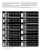
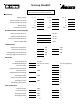
Indoor Blower motor speed tap selection may need to be modified
to accommodate normal continuous operation to prevent a nui-
sance trip. See following table.
Unit Model Number 5 8 10 15 20
*PH/*PC1424M41**
M
(F)
M
(F)
M
(F)
HNA
*PH/*PC1430M41**
M
(F)
M
(F)
M
(F)
HNA
*PH/*PC1436M41**
MMH
(F)
H
(F)
NA
*PH/*PC1442M41**
MMH
(F)
H
(F)
NA
*PH/*PC1448M41**
3
(F)
3
(F)
3
(F)
3
(F)
3
(F)
*PH/*PC1460M41**
3
(F)
3
(F)
3
(F)
3
(F)
3
(F)
*(F) - Factory Setting
3 speed (H)igh/(M)edium/(L)ow : PSC motor
4 speed (H)igh/(ML)Medium Low / (MH) Medium High/(L)ow : PSC motor
1/2/3/4/5: EEM motor
Electric Heat KW
Speed Taps Description: H / 4, 5 - High; M / 2, 3 - Medium; L / 1 - Low
MAINTENANCE
WARNING
HIGH VOLTAGE!
DISCONNECT ALL POWER BEFORE SERVICING OR INSTALLING
THIS UNIT.
MULTIPLE POWER SOURCES MAY BE PRESENT. FAILURE
TO DO SO MAY CAUSE PROPERTY DAMAGE, PERSONAL INJURY OR
DEATH.
The Self Contained Package Air Conditioner and Heat Pump should
operate for many years without excessive service calls if the unit is
installed properly. However it is recommended that the homeowner
inspect the unit before a seasonal start up. The coils should be
free of debris so adequate airflow is achieved. The return and
supply registers should be free of any obstructions. The filters
should be cleaned or replaced. These few steps will help to keep
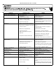
the product up time to a maximum. The Troubleshooting Chart (on
page 14) should help in identifying problems if the unit does not
operate properly.