INSTALLATION INSTRUCTIONS A/GPD 14 SEER “M” SERIES - SINGLE PACKAGE DUAL FUEL GAS-ELECTRIC HEATING & COOLING UNITS Affix this manual and Users Information Manual adjacent to the unit. ATTENTION INSTALLING PERSONNEL Prior to installation, thoroughly familiarize yourself with this Installation Manual. Observe all safety warnings. During installation or repair, caution is to be observed. It is your responsibility to install the product safely and to educate the customer on its safe use.
INDEX (continued) INDEX CONDENSATE DRAIN ................................................... 14 CONDENSATE DRAIN CONNECTION ................................. 14 NORMAL SEQUENCES OF OPERATION .............................. 14 HEAT PUMP OPERATION .............................................. 14 TO THE INSTALLER ..................................................... 2 TO THE OWNER ......................................................... 2 SHIPPING INSPECTION .................................................
FIRE OR EXPLOSION HAZARD Failure to follow the safety warnings exactly could result in serious injury, death or property damage. Never test for gas leaks with an open flame. Use a commercially available soap solution made specifically for the detection of leaks to check all connections. A fire or explosion may result causing property damage, personal injury or loss of life.
AVERTISSEMENT RISQUE D'INTOXICATION AU MONOXYDE DE CARBONESi les étapes décrites ci-dessous ne sont pas suivies pour chacun des appareils raccordés au système de ventilation au moment de sa mise en marche, cela peut entraîner une intoxication au monoxyde de carbone ou la mort.
RISQUE D'EMPOISONNEMENT AU MONOXYDE DE CARBONE Advertencia especial para la instalación de calentadores ó manejadoras de aire en áreas cerradas como estacionamientos ó cuartos de servicio. Las emisiones de monóxido de carbono pueden circular a través del aparato cuando se opera en cualquier modo. CO can cause serious illness including permanent brain damage or death.
PRE-INSTALLATION CHECKS Before attempting any installation, the following points should be considered: • Structural strength of supporting members • Clearances and provision for servicing • Power supply and wiring • Air duct connections • Drain facilities and connections • Gas piping and connections • Location may be on any four sides of a home, manufactured or modular, to minimize noise UNIT INSTALLATION ALL INSTALLATIONS: • For proper flame pattern within the heat exchanger and proper condensate drainage
ROOFTOP INSTALLATIONS ONLY: NOTE: To ensure proper condensate drainage, unit must be installed in a level position. • To avoid possible property damage or personal injury, the roof must have sufficient structural strength to carry the weight of the unit(s) and snow or water loads as required by local codes. Consult a structural engineer to determine the weight capabilities of the roof. • The unit may be installed directly on wood floors or on Class A, Class B, or Class C roof covering material.
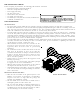
RIGGING DETAILS Refer to the Unit Installation Instructions for proper unit installation. Curbing must be installed in compliance with the National Roofing Contractors Association Manual. Lower unit carefully onto roof mounting curb. While rigging unit, center of gravity will cause condenser end to be lower than supply air end. GAS PIPING IMPORTANT NOTE: This unit is factory set to operate on natural gas at the altitudes shown on the rating plate.
Natural Gas Connection Natural Gas Capacity of Pipe in Cubic Feet of Gas Per Hour (CFH) Refer to the Proper Piping Practice drawing for the general layout at Nominal Black Pipe Size (inches) the unit. The following rules apply: Length of 1. Use black iron pipe and fittings for the supply piping. The use Pipe in Feet 1 1/2 3/4 1 1/4 1 1/2 of a flex connector and/or copper piping is permitted as long 10 132 278 520 1050 1600 20 92 190 350 730 1100 as it is in agreement with local codes.
Propane Gas Installations IMPORTANT NOTE: Propane gas conversion kits must be installed to convert units to propane gas. Refer to the gas piping section for the correct LP kit for conversion. All propane gas equipment must conform to the safety standards of the National Board of Fire Underwriters (See NBFU Manual 58). For satisfactory operation, propane gas supply pressure must be within 9.7 - 10.3 inches W.C. at the manifold with all gas appliances in operation.
WIRING NOTE: All wiring should be made in accordance with the National Electrical Code. Consult your local Power Company to determine the availability of sufficient power to operate the unit. Check the voltage, frequency, and phase at the power supply to ensure it corresponds to the unit’s RATED VOLTAGE REQUIREMENT. In accordance with the N.E.C. or local codes, install a branch circuit fused disconnect near the unit.
For unit protection, use a fuse or HACR circuit breaker that is in excess of the circuit ampacity, but less than or equal to the maximum overcurrent protection device. DO NOT EXCEED THE MAXIMUM OVERCURRENT DEVICE SIZE SHOWN ON UNIT DATA PLATE. All line voltage connections must be made through weatherproof fittings. All exterior power supply and ground wiring must be in approved weatherproof conduit. Low voltage wiring from the unit control panel to the thermostat requires coded cable.
The supply duct from the unit through a wall may be installed without clearance. However, minimum unit clearances as shown in the appendix must be maintained. The supply duct should be provided with an access panel large enough to inspect the air chamber downstream of the heat exchanger. A cover should be tightly attached to prevent air leaks. For duct flange dimensions on the unit refer to the Unit Dimension illustration in the appendix.
CONDENSATE DRAIN DRAIN CONNECTION CONDENSATE DRAIN CONNECTION A 3/4” NPT drain connection is supplied for condensate piping. An external trap must be installed for proper condensate drainage. UNIT 2" MINIMUM FLEXIBLE TUBING-HOSE OR PIPE 3" MINIMUM NORMAL SEQUENCES OF OPERATION A POSITIVE LIQUID SEAL IS REQUIRED HEAT PUMP OPERATION Drain Connection OUTDOOR THERMOSTAT For optimal performance, a dual fuel thermostat with an outdoor temperature sensor should be used.
DEFROST CYCLE NOTE: The defrost board is equipped with a jumper for SmartShift™ defrost technology operation. This operation turns the compressor off for 30 seconds at defrost initiation and termination. The unit is factory shipped for SmartShift™ defrost technology operation. To operate unit at rated efficiencies, move the jumper on the defrost board from “DLY” to “NORM”.
START-UP, ADJUSTMENTS, AND CHECKS HEATING START-UP ( NATURAL GAS / LP) This unit is equipped with an electronic ignition device to automatically light the main burners. It also has a power vent blower to exhaust combustion products. On new installations, or if a major component has been replaced, the operation of the unit must be checked. Check unit operation as outlined in the following instructions.
Gas Supply And Manifold Check Gas supply pressure and manifold pressure with the burners operating must be as specified on the rating plate. Gas Inlet Pressure Check Gas inlet pressure must be checked and adjusted in accordance to the type of fuel being consumed. With Power And Gas Off: 1. Connect a water manometer or adequate gauge to the inlet pressure tap of the gas valve. Inlet gas pressure can also be measured by removing the cap from the drip leg and installing a predrilled cap with a hose fitting.
Temperature Rise Check Check the temperature rise through the unit by placing thermometers in supply and return air registers as close to the unit as possible. Thermometers must not be able to sample temperature directly from the unit heat exchangers, or false readings could be obtained. 1. All registers must be open; all duct dampers must be in their final (fully or partially open) position and the unit operated for 15 minutes before taking readings. 2.
COOLING START-UP NOTE: Check all manual reset limit controls in heating circuit if cooling mode does not operate. Compressor Protection Devices The compressor includes components which are designed to protect the compressor against abnormal operating conditions. Refrigerant Charge Check (Units with Fixed Orifice Devices) After completing airflow measurements and adjustments the unit’s refrigerant charge must be checked.
3. Remove the flue from the induced draft blower and the collector box cover from the partition panel. 4. The primary heat exchanger tubes can be cleaned using a round wire brush attached to a length of high grade stainless steel cable, such as drain cleanout cable. Attach a variable speed reversible drill to the other end of the spring cable. Slowly rotate the cable with the drill and insert it into one of the primary heat exchanger tubes.
APPENDIX 21
TROUBLESHOOTING DIAGNOSTIC LED - RED STATUS ON NORMAL OPERATION OFF NO POWER OR INTERNAL CONTROL FAULT 1 FLASH IGNITION FAILURE 2 FLASHES PRESSURE SWITCH OPEN 3 FLASHES PRESSURE SWITCH CLOSED WITHOUT INDUCER ON 4 FLASHES OPEN LIMIT SWITCH CHECK CHECK INPUT POWER CHECK FUSE(S) GAS FLOW GAS PRESSURE GAS VALVE FLAME SENSOR CHECK PRESSURE SWITCH CHECK TUBING CHECK VENT MOTOR CHECK PRESSURE SWITCH CHECK WIRING FOR SHORTS CHECK MAIN LIMIT SWITCH CHECK AUXILIARY LIMIT SW. CHECK ROLLOUT LIMIT SW.
IGNITION CONTROL DIAGNOSTIC INDICATOR CHART Red Light Signal Off 1 Flash 2 Flashes 3 Flashes 4 Flashes 5 Flashes 6 Flashes 7 Flashes 8 Flashes 9 Flashes Amber Light Signal Off On 1 Flash 2 Flashes Refer to Abnormal Heating or Cooling Operation Sections of this Manual Internal Control Failure External Lockout Pressure Switch Stuck Open Pressure Switch Stuck Closed Thermal Protection Device Open Flame Detected with Gas Valve Closed Short Cycle Compressor Delay (Cooling Only) Limit Opened Five (5) Times Withi
UNIT DIMENSIONS 47 51 FLUE EXHAUST HOOD 18 7/16 16 FLUE EXHAUST 1 3/8 C A 5 1/2 16 7 15/16 B SUCTION/LIQUID PRESSURE PORTS BEHIND COMPRESSOR ACCESS PANEL 2 3/4 COMBUSTION AIR INTAKE RETURN B HEAT EXCHANGE ACCESS PANEL 4 3/4 GAS SUPPLY ENTRANCE SUPPLY 3 CONDENSATE DRAIN CONNECTION 3/4" NPT FEMALE EVAPORATOR/CONTROL PANEL ACCESS PANEL 16 1/8 19 1/8 OF ER Y NT VIT E A C R G 7 5/16 7 7/8 20 24 DIMENSION (INCHES) MEDIUM LARGE A B 32 16 40 18 C 9 1/2 14 POWER WIRE ENTRANCE CONTROL
[A/G]PD14[24-48]***M41** WIRING DIAGRAM CH RD BK GR BK RD RD BK BK BR YL BK PU PU SEE NOTE 7 S R C PU BR CM BL YL H C F LPS BL YL YL Y BK RD RD HIGH VOLTAGE! DISCONNECT ALL POWER BEFORE SERVICING. MULTIPLE POWER SOURCES MAY BE PRESENT. F AILURE TO DO SO MAY CAUSE PROPERTY DAMAGE, PERSONAL INJURY OR DEATH.
[A/G]PD14[24-48]***M41** SUPPLY VOLTAGE 208-230/1/6 0 L1 L2 COMPONENT LEGEND SEE NOTE 7 CH R C COMP H RCCF C S DC LO F CM DF2 DF1 HVDR IIC C T2 T1 C L1 ALS C CH CHS CM COMP DC DFT DR EM F FS GND GV HPS IIC IGN LPS LS OTP P1 P2 PS RCCF RS RVC TR VM CHS SEE NOTE 8 IIC PARK ODF L2 HI L2 LO INDUCER L2 VM HI SEE NOTE 3 L2 EM L1 SEE NOTE 2 F 2 L1 3 P1 TR L2 1 HIGH VOLTAGE! DISCONNECT ALL POWER BEFORE SERVICING. MULTIPLE POWER SOURCES MAY BE PRESENT.
MINIMUM CLEARANCES Clearance in accordance with local installation codes, the requirements of the gas supplier and the manufacturer’s installation instructions. Dégaugement conforme aux codes d’installation locaux, aux exigences du fournisseur de gaz et aux instructions d’installation du fabricant NOTE: Roof overhang should be no more than 36". RECOMMENDED FILTER SIZES UNIT 2 Ton 2 1/2 Ton 3 Ton 3 1/2 / 4 Ton Min.
THIS PAGE LEFT INTENTIONALLY BLANK 28
BLOWER PERFORMANCE DATA *PD1424060M41A* - Rise Range: 35° - 65° E.S.P T1 T2 T3 T4 T5 1 Stage Heating Speed CFM WATTS RISE 2 Stage Heating Speed CFM WATTS RISE Cooling Speed Cooling Speed Cooling Speed ST nd CFM WATTS CFM WATTS CFM 0.1 616 51 55 845 105 53 859 94 885 103 1048 WATTS 140 0.2 581 60 58 809 116 56 810 102 836 111 999 148 0.3 535 69 63 774 124 58 761 109 788 118 950 155 0.4 476 79 X 736 134 61 713 117 740 126 901 163 0.
BLOWER PERFORMANCE DATA *PD1436080M41A* - Rise Range: 35° - 65° T2 T1 E.S.P 0.1 0.2 0.3 0.4 0.5 0.6 0.7 0.
BLOWER PERFORMANCE DATA *PD1442115M41B* - Rise Range: 45° - 75° F T1 T2 T3 T4 T5 1 Stage Heating Speed CFM WATTS RISE 2 Stage Heating Speed CFM WATTS RISE Cooling Speed Cooling Speed Cooling Speed CFM WATTS CFM WATTS CFM WATTS 0.1 1090 150 52 1286 231 57 1354 260 1501 320 1609 365 0.2 1025 158 57 1225 239 61 1296 267 1446 328 1556 373 0.3 960 166 62 1165 247 64 1237 275 1391 336 1504 381 0.
Start-up Checklist Air Conditioning & Heating *Store in job file Date: ___________________________________ Location: __________________________________________ Model Number: ___________________________________ __________________________________________ Serial Number: ___________________________________ __________________________________________ Technician: ___________________________________ Unit #: __________________________________________ Pre Start-Up (Check each item as completed) Verify al
Start-up Checklist Air Conditioning & Heating Start-Up (Insert the values as each item is completed.) ELECTRICAL Supply Voltage L1 - L2 L2 - L3 L3 - L1 Circuit 1 Compressor Amps L1 L2 L3 Circuit 2 Compressor Amps L1 L2 L3 Blower Amps L1 L2 L3 Condenser Fan Amps Fan 1 Fan 2 Fan 3 BLOWER EXTERNAL STATIC PRESSURE Return Air Static Pressure IN. W.C. Supply Air Static Pressure IN. W.C. Total External Static Pressure IN. W.C.
THIS PAGE LEFT INTENTIONALLY BLANK 34
THIS PAGE LEFT INTENTIONALLY BLANK 35
CUSTOMER FEEDBACK We are very interested in all product comments. Please fill out the feedback form on one of the following links: Goodman® Brand Products: (http://www.goodmanmfg.com/about/contact-us). Amana® Brand Products: (http://www.amana-hac.com/about-us/contact-us). You can also scan the QR code on the right for the product brand you purchased to be directed to the feedback page. PRODUCT REGISTRATION Thank you for your recent purchase.