
GPD14 Installation Instructions


23
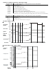
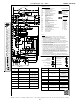
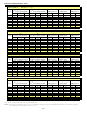
HEATING TIMING CHART
COOLING/HEAT PUMP TIMING CHART
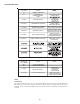
Red Light Signal Refer to Abnormal Heating or Cooling Operation Sections of this Manual
Off Internal Control Failure
1 Flash External Lockout
2 Flashes Pressure Switch Stuck Open
3 Flashes Pressure Switch Stuck Closed
4 Flashes Thermal Protection Device Open
5 Flashes Flame Detected with Gas Valve Closed
6 Flashes Short Cycle Compressor Delay (Cooling Only)
7 Flashes Limit Opened Five (5) Times Within The Same Call For Heat
8 Flashes Indoor/Outdoor Thermostat Open (Cooling Only; Devices Not present On All Models)
9 Flashes High Pressure/Loss of Charge Switch Open (Cooling Only; Devices Not Present On All Models)
Amber Light Signal Refer to Abnormal Heating or Cooling Operation Sections of this Manual
Off No Flame Present
On Normal Flame
1 Flash Low Flame Current
2 Flashes Flame Detected with Gas Valve De-energized.
90, 120, 150, 180
Circulator
Blower
HIGH
OFF
Seconds
Gas Valve
Igniter
Induced
Draft
Blower
Thermostat
0 15 22 27 52 0 30
LOW
HIGH
OFF
LOW
OFF
ON
HIGH
OFF
LOW
HIGH
OFF
LOW
Circulator
Blower
Compressor
Outdoor Fan
HIGH
OFF
LOW
HIGH
OFF
LOW
HIGH
OFF
LOW
IGNITION CONTROL DIAGNOSTIC INDICATOR CHART