Service Instructions APG/GPG 14 SEER Gas Electric Package Units with R-410A Refrigerant & Accessories This Forced Air Central Unit Design Complies With Requirements Embodied in The American National Standard / National Standard of Canada Shown Below. ANSI Z21.47•CSA-2.3 Central Furnaces This manual is to be used by qualified, professionally trained HVAC technicians only.
TABLE OF CONTENTS IMPORTANT INFORMATION ......................... 2 - 3 SCHEDULED MAINTENANCE .................. 29 - 31 PRODUCTION IDENTIFICATION .................. 4 - 5 SERVICING TABLE OF CONTENTS ............... 34 ACCESSORIES ........................................... 6 - 13 SERVICING ................................................ 32 - 60 PRODUCT DESIGN .................................. 14 - 19 ACCESSORIES WIRING DIAGRAMS .............. 61 SYSTEM OPERATION ..............................
IMPORTANT INFORMATION SAFE REFRIGERANT HANDLING While these items will not cover every conceivable situation, they should serve as a useful guide. WARNING Refrigerants are heavier than air. They can "push out" the oxygen in your lungs or in any enclosed space.To avoid possible difficulty in breathing or death: • Never purge refrigerant into an enclosed room or space. By law, all refrigerants must be reclaimed. • If an indoor leak is suspected, thoroughly ventilate the area before beginning work.
PRODUCT IDENTIFICATION The model number is used for positive identification of component parts used in manufacturing. Please use this number when requesting service or parts information.
PRODUCT IDENTIFICATION Single Phase Package Gas Units Model # Description APG14[24-60]***M41AA Amana® Brand Package Gas 14 Seer R410A Multi-Position gas/electric units. Initial release of single phase models. APG1461***M41AA Amana® Brand Package Gas 14 Seer R410A Multi-Position gas/electric units. Release of 5 Ton single phase models with a compressor change. APG14[24-60]***M41AB Amana® Brand Package Gas 14 Seer R410A Multi-Position gas/electric units.
ACCESSORIES Part Number 0259G00214 0259L00412 CDK36 CDK36515 CDK36530 CDK36535 CDK4872 CDK4872515 CDK4872530 CDK4872535 D14CRBPGCHMA DDNIFRPGMM DDNIFRPGA DHZECNJPGCHM DHZECNJPGCHL DHZIFRPGCHA DPHFRA HA-03 LPM-07 LPM-08 PGEDJ101/102 PGEDJ103 PGMDD101/102 PGMDD103 PGMDH102 PGMDH103 PGMDMD101/102 PGMDMD103 PGMDMH102 PGMDMH103 SQRPG101/102 SQRPG103 SQRPGH101/102 SQRPGH103 ACCESSORIES - A/GPG14 Models Description Economizer Wiring Harness (2-4 Ton) Economizer Wiring Harness (5 Ton) Flush Mount Concentric Duct K
LIGHTING INSTRUCTIONS A/GPG14[24-48]***M41AA FOR YOUR SAFETY READ BEFORE OPERATI NG If you do not follow these instructions exactly, a fire or explosion may result causing property damage, personal injury or loss of life. A. This appliance does not have a pilot. It is equipped with an ignition device which automatically lights the burners. Do not try to light the burners by hand. B. BEFORE OPERATING smell all around the appliance area for gas.
LIGHTING INSTRUCTIONS FOR YOUR SAFETY READ BEFORE OPERATING WARNING: If you do not follow these instructions exactly,a fire or explosion may result causing property damage, personal injury or loss of life. A. This appliance does not have a pilot. It is equipped with an ignition device which automatically lights the burner. Do not try to light the burner by hand. B. BEFORE OPERATING smell all around the appliance area for gas.
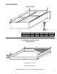
ACCESSORIES ROOF CURBS B S R A C 1 5/8 14 1/2 1 3/8 MODEL A B C D14CRBPGCHMA 46 1/4 39 3/8 14 1/2 RETURN SUPPLY 12 1/2 x 23 15 x 22 1/2 DOWNFLOW FILTER RACK (DDNIFRPGA) 25 1 1/2 3 14 2 26 1/2 Filter Size: 14" x 25" x 2" Measurement in inches. NOTE: DDNIFRPGA cannot be used with downflow economizers.
ACCESSORIES PGEDJ101/102 (DOWNFLOW ECONOMIZER) E C D F A B PGEDJ101/102 A 20 B 16.25 C 16 D 23.5 E 12.5 F 45.
ACCESSORIES ECONOMIZER (HORIZONTAL APPLICATIONS) B 16 1/8 18 D A E C Measurement in inches.
ACCESSORIES MOTORIZED/MANUAL FRESH AIR DAMPERS (DOWNFLOW APPLICATIONS) BOTTOM VIEW 12 1/8 6 5 3/4 10 A 11 7/8 1 PGMDD103 B BOTTOM VIEW 12 1/8 5 3/4 6 10 A 11 7/8 1 B MANUAL PGMDD101/102 MODEL A B PGMDD101/102 16 16 PGMDD103 18 16 MOTORIZED B MODEL A B PGMDMD101/102 16 16 PGMDMD103 18 16 A SQUARE TO ROUND CONVERTER (DOWNFLOW APPLICATIONS) 12 1/4 14 3/4 C D S 16 ø 22 3/4 16 ø 22 1/4 R A 12 1/4 14 3/4 B 22 3/4 12 22 1/4 18 ø 18 ø MODEL A B C D RETURN S
ACCESSORIES SQUARE TO ROUND CONVERTER (HORIZONTAL APPLICATIONS) B C A MODEL A B C SQRPGH101/102 16 16 1/2 16 1/2 SQRPGH103 18 18 1/2 18 1/2 Measurements are in inches.
PRODUCT DESIGN Locations and Clearances NOTE: To ensure proper condensate drainage, unit must be installed in a level position. In installations where the unit is installed above ground level and not serviceable from the ground (Example: Roof Top installations) the installer must provide a service platform for the service person with rails or guards in accordance with local codes or ordinances or in their absence with the latest edition of the National Fuel Gas Code ANSI Z223.1.
PRODUCT DESIGN A 3/4" - 14 NPT drain connector is provided for removal of condensate water from the indoor coil. In order to provide proper condensate flow, do not reduce the drain line size. NOTE: Tighten drain to a maximum torque of 10 in-lbs. Refrigerant flow control is achieved by use of thermostatic expansion valves (TXV) or flowrator. The single phase models use permanent split capacitors (PSC) design compressors. Starting components are therefore not required.
PRODUCT DESIGN WARNING DO NOT EXCEED THE MAXIMUM OVERCURRENT DEVICE SIZE SHOWN ON THE UNIT DATA PLATE. All line voltage connections must be made through weather proof fittings. All exterior power supply and ground wiring must be in approved weather proof conduit. Low voltage wiring from the unit control panel to the thermostat requires coded cable. See the following figures for ground level and rooftop wiring. Note: Junction box location shown is optional and is for illustration purposes only.
PRODUCT DESIGN GAS SUPPLY AND PIPING NATURAL GAS CAPACITY OF PIPE IN CUBIC FEET OF GAS PER HOUR (CFH) LENGTH OF PIPE IN FEET CAUTION 10 20 30 40 50 60 70 80 90 100 THIS PACKAGE GAS UNIT IS FACTORY SET TO OPERATE ON NATURAL GAS AT THE ALTITUDES SHOWN ON THE RATING PLATE. IF OPERATION ON PROPANE IS REQUIRED, OBTAIN AND INSTALL THE PROPER CONVERSION KIT(S) BEFORE OPERATING THIS UNIT. FAILURE TO DO SO MAY RESULT IN UNSATISFACTORY OPERATION AND/OR EQUIPMENT DAMAGE.
PRODUCT DESIGN TANKS AND PIPING - PROPANE UNITS WARNING MANUAL SHUT-OFF VALVE DRIP LEG GROUND JOINT UNION (INSTALLED AHEAD OF GAS VALVE) PERSONAL INJURY HAZARD IRON OXIDE (RUST) CAN REDUCE THE LEVEL OF ODORANT IN PROPANE GAS. A GAS DETECTING DEVICE IS THE ONLY RELIABLE METHOD TO DETECT A PROPANE GAS LEAK. CONTACT YOUR LOCAL PROPANE SUPPLIER ABOUT INSTALLING A GAS DETECTING WARNING DEVICE TO ALERT YOU IN THE EVENT THAT A GAS LEAK SHOULD DEVELOP.
PRODUCT DESIGN PROPANE GAS PIPING CHARTS TYPICAL PROPANE PIPING 5 to 15 PSIG (20 PSIG Max.) First Stage Regulator 200 PSIG Maximum Sizing Between First and Second Stage Regulator Maximum Propane Capacities listed are based on 1 PSIG Pressure Drop at 10 PSIG Setting. Capacities in 1,000 BTU/HR Continuous 11" W.C. PIPE OR TUBING LENGTH, FEET Second Stage Regulator WARNING NOMINAL PIPE SIZE, SCHEDULE 40 TUBING SIZE, O.D.
SYSTEM OPERATION COOLING HEATING The refrigerant used in the system is R-410A. It is a clear, colorless, non-toxic and non-irritating liquid. R-410A is a 50:50 blend of R-32 and R-125. The boiling point at atmospheric pressure is -62.9°F. The heating cycle is accomplished by using a unique tubular design heat exchanger which provides efficient gas heating on either natural gas or propane gas fuels.
A/GPG14 SYSTEM OPERATION PCBAG123 IGNITION CONTROL SEQUENCE OF OPERATION Continous Fan 1. When the thermostat calls for continuous fan (G) with out a call for heat or cooling, the indoor the fan has a 7 second delay on make and energizes the “HEAT” speed. The fan remains energized as long as the call for fan remains without a call for heat or cooling. The fan call “G” has a 60 second delay on break.
SYSTEM OPERATION Pin 1 2 3 4 5 6 7 8 9 10 11 12 Voltage 24VAC 24VAC 24VAC 24VAC 24VAC 24VAC 24VAC 24VAC 24VAC 24VAC 24VAC 24VAC Function 24VAC Input (from Transformer) 24VAC Common (Chassis Ground) Gas Valve Output Limit Switch Output Limit Switch Input (Common with Pin 9) Pressure Switch Input Thermostat Fan (G) Input Pressure Switch Output (Common with Pin 10) Thermostat "R" (Common with Pin 5) Thermostat Heat Input (W) (Common with Pin 8) Thermostat Cool Input (Y) Compressor Contactor Output Table 1:
A/GPG14 SYSTEM OPERATION PCBAG127 IGNITION CONTROL SEQUENCE OF OPERATION A. Heating Operation: Low stage heat B. Heating Operation: High stage heat 1. Thermostat type is set to two-stage. 1. Thermostat type is set to two-stage. 2. Thermostat “W1” input initiates low stage heating. 2. 3. Induced draft blower is energized at high speed for the pre-purge period. Pre-purge timer begins after control recognizes pressure switch has closed. Thermostat “W1” and “W2” inputs initiate high stage heating.
A/GPG14 SYSTEM OPERATION PCBAG127 IGNITION CONTROL SEQUENCE OF OPERATION (CONT.) A. Cooling Operation: Low stage cool 1. Thermostat type is set to two-stage. 2. Thermostat “Y1” or thermostat “Y1” and “G” input initiates low stage cooling. 3. Low and high stage compressor outputs are energized. 2. Condenser fan motor is energized at high speed. 3. Air circulating blower is energized at high cool speed after cool ON delay expires. Cool ON delay timer begins when thermostat inputs are detected.
SYSTEM OPERATION The following tables list the functions for the connectors and terminals, the timings, and the fault codes for the PCBAG127 control board. PCBAG127 CONTROL BOARD DESCRIPTION The ignition control is designed for use in gas heating/electric cooling package equipment (rooftop applications) and operates with a two stage heat and two stage cooling system. It is a direct spark ignition system that uses a 22,000 volt spark to ignite the burners. A flame sensor is used to monitor the flame.
SYSTEM OPERATION Pin Voltage Function 1 24VAC Indoor/Outdoor Thermostat (IDT/ODT) Output 2 24VAC High Stage Compressor Output 3 24VAC Pressure Switch/Loss of Charge Switch Input 4 24VAC Indoor/Outdoor Thermostat (IDT/ODT) Input 5 24VAC Pressure Switch/Loss of Charge Switch Output 6 24VAC Low Stage Compressor Output Table 1: Circuit Definitions and Voltage Ratings for the 6-Circuit Connector Circuits Pin Voltage 1 24VAC Limit Switch Output Function 2 24VAC 24VAC Input to Control
SYSTEM OPERATION Period Timing Pre-Purge 15 Seconds Inter-Purge 30 Seconds Post Purge 30 Seconds Trial-for-Ignition (TFI) 7 Seconds Flame Stabilization Period 10 Seconds Flame Failure Response Time 2 Seconds within Flame Stabilization Period 2 Seconds or Per ANSI Z21.
SYSTEM OPERATION Typical Package Cooling or Package Gas Indoor Coil Outdoor Coil Thermostatic Expansion Valve Restrictor Orifice Assy Either a thermostatic expansion valve or restrictor orifice assembly may be used depending on model, refer to the parts catalog for the model being serviced. Restrictor Orifice Assembly in Cooling Operation In the cooling mode the orifice is pushed into its seat forcing refrigerant to flow through the metered hole in the center of the orifice.
SCHEDULED MAINTENANCE Package gas units require regularly scheduled maintenance to preserve high performance standards, prolong the service life of the equipment, and lessen the chances of costly failure. In many instances the owner may be able to perform some of the maintenance; however, the advantage of a service contract, which places all maintenance in the hands of a trained serviceman, should be pointed out to the owner. 10. Start the system and run a Heating Performance Test.
SCHEDULED MAINTENANCE 1 0 9 2 8 3 1 1 9 8 2 5 1 Million 6 6 5 4 100 Thousand Quarter 8 8 2 3 7 7 4 5 6 10 Thousand 6 5 4 1 Thousand CUBIC FEET One Foot Foot 1 9 9 2 3 3 7 7 4 0 GAS RATE -- CUBIC FEET PER HOUR 30 Seconds for One Revolution 1/4 cu/ft 10 11 12 13 14 15 16 17 18 19 20 21 22 23 24 25 26 27 28 29 30 31 32 33 34 35 90 82 75 69 64 60 56 53 50 47 45 43 41 39 37 36 34 33 32 31 30 -28 -26 -- Size of Test Dial 1/2 1 2 cu/ft cu/ft cu/ft 5 cu/ft Seconds for
SCHEDULED MAINTENANCE Example: It takes forty-five (45) seconds on the gas meter for the hand on the cubic foot dial to make one complete revolution, with all appliances off, except the unit. Using the gas rate chart, observe the forty-five (45) seconds, locate and read across to the one (1) cubic foot dial column. There you will find the number 80, which shows that eighty (80) cubic feet of gas will be consumed in one (1) hour.
SERVICING COOLING ANALYSIS CHART Pow er Failure Blow n Fuse Loose Connection Shorted or Broken Wires Open Overload Faulty Thermostat Faulty Transf ormer Shorted or Open Capacitor Shorted or Grounded Compressor Compressor Stuck Faulty Compressor Contactor 2nd Stage Compressor Not Energized Faulty Ignition Control Open Control Circuit Low Voltage Faulty Evap.
SERVICING GAS HEATING ANALYSIS CHART Pow er Failure Blow n Fuse Loose Connection Shorted or Broken Wires No Low V oltage Faulty Thermostat Faulty Transf ormer Poor or High Resistance Ground Improper Heat A nticipator Setting Improper Thermostat Location Faulty Limit or Roll Out Sw itch Faulty Flame Sensor Faulty Ignition Control Gas V alve or Gas Supply Shut Of f Faulty Induced Draf t Blow er Dirty Flame Sensor, Low uA Flame Sensor not in Flame, Low uA Faulty Gas V alve No High Stage Heat (2 Stage Only) Op
SERVICING Table of Contents S-1 S-2 S-3 S-3A S-3B S-3C S-4 S-7 S-8 S-9 S-12 S-13 S-15 S-15A S-15B S-16C S-16D S-17 S-17A S-17B S-17D S-18 S-100 S-101 S-102 S-103 S-104 Checking Voltage .......................................... 35 Checking Wiring ............................................ 36 Checking Thermostat, Wiring & Anticipator .. 36 Thermostat & Wiring ..................................... 36 Cooling Anticipator ........................................ 36 Heating Anticipator .......................
SERVICING S-1 CHECKING VOLTAGE HIGH VOLTAGE! Disconnect ALL power before servicing or installing this unit. Multiple power sources may be present. Failure to do so may cause property damage, personal injury or death. Three phase units require a balanced 3 phase power supply to operate. If the percentage of voltage imbalance exceeds 3% the unit must not be operated until the voltage condition is corrected. % Voltage = Imbalance Max.
SERVICING If the imbalance had not changed then the problem would lie within the equipment. Check for current leakage, shorted motors, etc. S-2 CHECKING WIRING WARNING Line Voltage now present. 1. Set fan selector switch at thermostat to "ON" position. 2. With voltmeter, check for 24 volts at wires C and G. HIGH VOLTAGE! Disconnect ALL power before servicing or installing this unit. Multiple power sources may be present. Failure to do so may cause property damage, personal injury or death. 1.
SERVICING S-4 CHECKING TRANSFORMER AND CONTROL CIRCUIT NOTE: Most single phase contactors break only one side of the line (L1), leaving 115 volts to ground present at most internal components. 1. Remove the leads from the holding coil. 2. Using an ohmmeter, test across the coil terminals. HIGH VOLTAGE! Disconnect ALL power before servicing or installing this unit. Multiple power sources may be present. Failure to do so may cause property damage, personal injury or death.
SERVICING S-9 CHECKING FAN RELAY CONTACTS The fan relays are incorporated into the control board. See section S-313 for checking control board. The low pressure control is designed to cut-out (open) at approximately 7 PSIG ± 3 PSIG. It will automatically cut-in (close) at approximately 25 PSIG ± 5 PSIG. Test for continuity using a VOM and if not as above, replace the control.
SERVICING RELAY, START A potential or voltage type relay is used to take the start capacitor out of the circuit once the motor comes up to speed. This type of relay is position sensitive. The normally closed contacts are wired in series with the start capacitor and the relay holding coil is wired parallel with the start winding. As the motor starts and comes up to speed, the increase in voltage across the start winding will energize the start relay holding coil and open the contacts to the start capacitor.
SERVICING S-16D CHECKING EEM MOTORS HIGH VOLTAGE! Disconnect ALL power before servicing or installing this unit. Multiple power sources may be present. Failure to do so may cause property damage, personal injury or death. 1. Remove the motor leads from its respective connection points and capacitor (if applicable). 2. Check the continuity between each of the motor leads. 3. Touch one probe of the ohmmeter to the motor frame (ground) and the other probe in turn to each lead.
SERVICING S-17 CHECKING COMPRESSOR WARNING Hermetic compressor electrical terminal venting can be dangerous. When insulating material which supports a hermetic compressor or electrical terminal suddenly disintegrates due to physical abuse or as a result of an electrical short between the terminal and the compressor housing, the terminal may be expelled, venting the vapor and liquid contents of the compressor housing and system.
SERVICING S-17B GROUND TEST If fuse, circuit breaker, ground fault protective device, etc., has tripped, this is a strong indication that an electrical problem exists and must be found and corrected. The circuit protective device rating must be checked, and its maximum rating should coincide with that marked on the equipment nameplate. With the terminal protective cover in place, it is acceptable to replace the fuse or reset the circuit breaker ONE TIME ONLY to see if it was just a nuisance opening.
SERVICING S-18 TESTING CRANKCASE HEATER (OPTIONAL ITEM) The crankcase heater must be energized a minimum of four (4) hours before the condensing unit is operated. Crankcase heaters are used to prevent migration or accumulation of refrigerant in the compressor crankcase during the off cycles and prevents liquid slugging or oil pumping on start up. A crankcase heater will not prevent compressor damage due to a floodback or over charge condition. WARNING Disconnect ALL power before servicing. 1.
SERVICING WARNING Do not front seat the service valve(s) with the compressor open, with the suction line of the comprssor closed or severely restricted. 1. Connect the vacuum pump, vacuum tight manifold set with high vacuum hoses, thermocouple vacuum gauge and charging cylinder as shown. 2. Start the vacuum pump and open the shut off valve to the high vacuum gauge manifold only.
SERVICING Charge the system with the exact amount of refrigerant. Refer to the specification section or check the unit nameplates for the correct refrigerant charge. The condition of the scroll flanks is checked in the following manner. 1. Attach gauges to the high and low side of the system. An inaccurately charged system will cause future problems. 2. Start the system and run a “Cooling Performance Test. 1. Using a quality set of charging scales, weigh the proper amount of refrigerant for the system.
SERVICING Pressure vs. Temperature Chart R-410A PSIG 12 14 16 18 20 22 24 26 28 30 32 34 36 38 40 42 44 46 48 50 52 54 56 58 60 62 64 66 68 70 72 74 76 78 80 82 84 86 88 90 92 94 96 98 100 102 104 106 108 110 112 °F -37.7 -34.7 -32.0 -29.4 -36.9 -24.5 -22.2 -20.0 -17.9 -15.8 -13.8 -11.9 -10.1 -8.3 -6.5 -4.5 -3.2 -1.6 0.0 1.5 3.0 4.5 5.9 7.3 8.6 10.0 11.3 12.6 13.8 15.1 16.3 17.5 18.7 19.8 21.0 22.1 23.2 24.3 25.4 26.4 27.4 28.5 29.5 30.5 31.2 32.2 33.2 34.1 35.1 35.5 36.9 PSIG 114.0 116.0 118.0 120.0 122.
SERVICING S-106 OVERFEEDING 3. Refer to the superheat table provided for proper system superheat. Add charge to lower superheat or recover charge to raise superheat. Overfeeding by the expansion valve results in high suction pressure, cold suction line, and possible liquid slugging of the compressor. Superheat Formula = Suct. Line Temp. - Sat. Suct. Temp. If these symptoms are observed: EXAMPLE: 1. Check for an overcharged unit by referring to the cooling performance charts in the servicing section.
SERVICING REQUIRED LIQUID LINE TEMPERATURE LIQUID PRESSURE AT SERVICE VALVE (PSIG) 189 195 202 208 215 222 229 236 243 251 259 266 274 283 291 299 308 317 326 335 345 354 364 374 384 395 406 416 427 439 450 462 474 486 499 511 48 8 58 60 62 64 66 68 70 72 74 76 78 80 82 84 86 88 90 92 94 96 98 100 102 104 106 108 110 112 114 116 118 120 122 124 126 128 REQUIRED SUBCOOLING TEMPERATURE (°F) 10 12 14 16 56 54 52 50 58 56 54 52 60 58 56 54 62 60 58 56 64 62 60 58 66 64 62 60 68 66 64 62 70 68 66 64 72 70 68
SERVICING S-109 CHECKING SUBCOOLING Refrigerant liquid is considered subcooled when its temperature is lower than the saturation temperature corresponding to its pressure. The degree of subcooling equals the degrees of temperature decrease below the saturation temperature at the existing pressure. 1. Attach an accurate thermometer or preferably a thermocouple type temperature tester to the liquid line close to the pressure switch. 2.
SERVICING S-112 CHECKING RESTRICTED LIQUID LINE S-115 COMPRESSOR BURNOUT When the system is operating, the liquid line is warm to the touch. If the liquid line is restricted, a definite temperature drop will be noticed at the point of restriction. In severe cases, frost will form at the restriction and extend down the line in the direction of the flow. When a compressor burns out, high temperature develops causing the refrigerant, oil and motor insulation to decompose forming acids and sludge.
SERVICING 6. Start up the unit and record the pressure drop across the drier. NOTE: Both readings may be taken simultaneously and read directly on the manometer if so desired. 7. Continue to run the system for a minimum of twelve (12) hours and recheck the pressure drop across the drier. Pressure drop should not exceed 6 PSIG. 4. Consult proper table for quantity of air. 8. Continue to run the system for several days, repeatedly checking pressure drop across the suction line drier.
SERVICING S-300 TESTING PRIMARY LIMIT CONTROL S-301 TESTING AUXILIARY LIMIT APG/GPG units use a snap-disk type primary limit device. Sometimes referred to as "stat on a stick". The limit setting is fixed and must not be readjusted in the field. The auxiliary limit control is a preset nonadjustable control mounted in the blower compartment area. Volt / Ohm Meter COLOR IDENTIFYING SLEEVES It is connected in series with the rollout switch wiring to the gas valve.
SERVICING CHECKING FLAME ROLLOUT SWITCH Limit Switch Operation (Applies to Primary, Auxiliary, and Roll Out Limits) DSI systems. V O LT / O H M M ET E R R ED R ES ET B U TT O N If a limit switch opens, the indoor blower is energized on heat speed and the induced draft blower is energized. The LED on the control flashes "4" to indicate an open limit switch. The blower and inducer remain on while the limit switch is open. The gas valve is de-energized.
SERVICING 5. Look under the heat shield as the unit is running. Flames should be drawn into firing tubes. a. If only one burners flame is not drawn into the tube, that tube is restricted. b. If, without the air circulation blower running, all flames are not drawn into the tubes either the collector box, combustion blower, or flue outlet is obstructed.
SERVICING Pressure Regulator (under cap screw) Outlet Pressure Tap Inlet Pressure Tap S-306 CHECKING ORIFICES A predetermined fixed gas orifice is used in all of these furnaces. That is an orifice which has a fixed bore and position.
SERVICING S-307 CHECKING GAS PRESSURE Gas inlet and manifold pressures should be checked and adjusted in accordance to the type of fuel being consumed. Pressure Regulator (under cap screw) Open to Atmosphere Open to Atmosphere WARNING Disconnect gas and electrical power supply. Inlet Pressure Tap 1. Connect a water manometer or adequate gauge to the inlet pressure fitting of the gas valve. 2.
SERVICING 2. Check burner for proper alignment and/or replace burner. 3. Improper orifice size - check orifice for obstruction. Manifold Gas Pressure Natural Gas 3.5" w.c. Propane Gas 10.0" w.c. S-310 CHECKING PRESSURE CONTROL Single Stage Gas Manifold Gas Pressure Range A pressure control device is used to measure negative pressure at the induced draft blower motor inlet to detect a partial or blocked flue. Nominal Natural Low Stage High Stage 1.6 - 2.2" w.c. 3.2 - 3.8" w.c. 2.0" w.c. 3.5" w.c.
SERVICING HOSE TO J-TUBE altitude range. High altitude kits are not approved for use in Canada. For installations above 2,000 feet, use kit HA-03. The HA-03 kit is used for both Natural and LP gas at high altitudes. 1/4" COPPER TEE Use LPM-08 (2 stage heat models) or LPM-07 (1 stage heat models) propane conversion kit for propane conversions at altitudes below 2000 feet. Natural gas installations below 2000 feet do not require a kit.
SERVICING Testing Direct Spark Ignition (DSI) Systems PCBAG127 Board PCBAG123 Ignition Board Fault Codes Status Light On Equipment Status Normal Operation Check Check Input Power, No Power or Check Fuse on Control, Internal Control Fault Replace Control Check Gas Flow, Ignition Failure, Check Gas Pressure, Open Rollout Switch, Check Gas Valve, or Open Aux. Limit Check Flame Sensor, Switch Check Flame Rollout, Check Aux. Limit.
SERVICING L2 L1 INDUCER LOW T1 OD F LOW HIGH PARK HIGH Flame Sensor K4 K6 Q3 FS K3 K5 T2 C9 K7 U1 P2 U2 Flame Sensor 2. Connect a microamp meter in series with this wire and terminal FS. U6 5 4 3 2 1 U7 K2 3. Be sure the negative side of the meter is to the wire and the positive of the meter is to terminal FS. K1 4. Turn on Power. U4 U3 U5 WARNING 180 SPEED UP 150 120 SW1 90 Line Voltage now present.
+ COM 3 2 1 (O) ORANGE O R (G) GREEN (O) ORANGE (R) RED 6 8 4 7 WHITE RED BLACK Y2 TSTAT Y1 TSTAT 1 Y/Y2 (CONTACTOR)(CC2) 2 3 COMMON Y1 (CONTACTOR) (CC1) 5 6 8 9 G WIRE LENGTHS FOR PLUG 2 PURPLE = 2 X 77" YELLOW = 2 X 77" BLUE = 1 X 77" GREEN = 1 X 77" 9 (Y) YELLOW (BL) BLUE (P) PURPLE 3 5 (P) PURPLE 2 4 (Y) YELLOW 1 COLOR CODES FOR PLUG 2 WIRE LENGTHS FOR PLUG 1 ORANGE = 1 X 78" GROUND = 1 X 50" GROUND (G)GREEN 8 COLOR CODES FOR PLUG 1 2...
A/GPG14[24-42]***M41** WIRING DIAGRAMS HIGH VOLTAGE! DISCONNECT ALL POWER BEFORE SERVICING OR INSTALLING THIS UNIT. MULTIPLE POWER SOURCES MAY BE PRESENT. FAILURE TO DO SO MAY CAUSE PROPERTY DAMAGE, PERSONAL INJURY OR DEATH.
A/GPG14[24-42]***M41** WIRING DIAGRAMS HIGH VOLTAGE! DISCONNECT ALL POWER BEFORE SERVICING OR INSTALLING THIS UNIT. MULTIPLE POWER SOURCES MAY BE PRESENT. FAILURE TO DO SO MAY CAUSE PROPERTY DAMAGE, PERSONAL INJURY OR DEATH.
WIRING DIAGRAMS A/GPG1448***M41A* HIGH VOLTAGE! DISCONNECT ALL POWER BEFORE SERVICING OR INSTALLING THIS UNIT. MULTIPLE POWER SOURCES MAY BE PRESENT. FAILURE TO DO SO MAY CAUSE PROPERTY DAMAGE, PERSONAL INJURY OR DEATH.
A/GPG1448***M41A* WIRING DIAGRAMS HIGH VOLTAGE! DISCONNECT ALL POWER BEFORE SERVICING OR INSTALLING THIS UNIT. MULTIPLE POWER SOURCES MAY BE PRESENT. FAILURE TO DO SO MAY CAUSE PROPERTY DAMAGE, PERSONAL INJURY OR DEATH.
WIRING DIAGRAMS A/GPG14[60/61]***M41A* HIGH VOLTAGE! DISCONNECT ALL POWER BEFORE SERVICING OR INSTALLING THIS UNIT. MULTIPLE POWER SOURCES MAY BE PRESENT. FAILURE TO DO SO MAY CAUSE PROPERTY DAMAGE, PERSONAL INJURY OR DEATH.
A/GPG14[60/61]***M41A* WIRING DIAGRAMS HIGH VOLTAGE! DISCONNECT ALL POWER BEFORE SERVICING OR INSTALLING THIS UNIT. MULTIPLE POWER SOURCES MAY BE PRESENT. FAILURE TO DO SO MAY CAUSE PROPERTY DAMAGE, PERSONAL INJURY OR DEATH.