
GPG14M Installation Manual

10
CAUTION
T
O PREVENT IMPROPER AND DANGEROUS OPERATION DUE TO WIRING ERRORS,
LABEL ALL WIRES PRIOR TO DISCONNECTION WHEN SERVICING CONTROLS.
V
ERIFY PROPER OPERATION AFTER SERVICING.
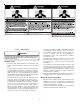
For unit protection, use a time delay fuse or HACR circuit
breaker that is in excess of the circuit ampacity, but less than
or equal to the maximum overcurrent protection device. DO
NOT EXCEED THE MAXIMUM OVERCURRENT DEVICE SIZE
SHOWN ON UNIT DATA PLATE.
All line voltage connections must be made through
weatherproof fittings. All exterior power supply and ground
wiring must be in approved weatherproof conduit. Low voltage
wiring from the unit control panel to the thermostat requires
coded cable. See below for ground level and rooftop wiring.
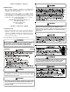
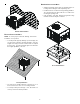
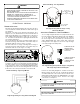
Electrical Power Directly To Junction Box
Electrical Power Routed Through Bottom of Unit
Note:Junction box location
shown is optional and is
for illustration purposes only.
JUNCTION BOX
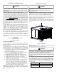
Typical Electrical Wiring Unit Voltage
UNIT VOLTAGE
The unit transformer is factory connected for 230V operation.
If the unit is to operate on 208V, reconnect the transformer
primary lead as shown on the unit wiring diagram.
HEAT A NTICIPATOR S ETTING
The heat anticipator is to be set by measuring the load
(amperage) at the “R” circuit. Follow the instructions provided
by the thermostat for more details.
CIRCULATING AIR AND FILTERS
AIRFLOW C ONVERSION
Units can easily be converted from horizontal to down-
discharge airflow delivery. In down-discharge or high static
installations, the installer should measure the total external
static and review the blower performance charts before
performing the installation. In some installations it will be
necessary to change the blower speed to provide proper air
flow.
Horizontal Air Flow
Single phase models are shipped without horizontal duct
covers. If needed, these kits may be ordered through
Goodman’s Service Parts department.
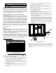
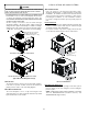
For 3-phase models only, remove supply and return duct
covers which are attached to the unit as shown below.
Remove these covers
for horizontal duct
applications
Duct Cover Installation
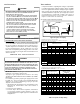
Down Discharge Applications
Cut insulation around bottom openings and remove panels
from the bottom of the unit, saving the screws holding the
panels in place.
NOTE: Single phase models require installation of horizontal
duct kit #20464501PDGK (medium chassis) and
#20464502PDGK (large chassis).
(3-phase models only)