
GPG14M Installation Manual

8
TANKS AND PIPING
Complete information regarding tank sizing for vaporization,
recommended regulator settings and pipe sizing is available
from most regulator manufacturers and propane gas suppliers.
Since propane gas will quickly dissolve white lead or most
standard commercial compounds, special pipe dope must be
used. Shellac base compounds resistant to the actions of
liquefied petroleum gases such as Gasolac
®
, Stalactic
®
,
Clyde’s
®
or John Crane
®
are satisfactory.
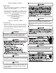
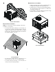
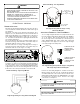
See below for typical propane gas piping.
200 PSIG
Maximum
5 to 15 PSIG
(20 PSIG Max.)
Continuous
11" W.C.
Second Stage
Regulator
First Stage
Regulator
Typical Propane Gas Piping
Sizing Between First and Second Stage Regulator
Maximum Propane Capacities listed are based on 1 PSIG Pressure Drop at 10
PSIG Setting. Capacities in 1,000 BTU/HR
3/8" 1/2" 5/8" 3/4" 7/8" 1/2" 3/4"
30 309 700 1,303 2,205 3,394 1,843 3,854
40 265 599 1,115 1,887 2,904 1,577 3,298
50 235 531 988 1,672 2,574 1,398 2,923
60 213 481 896 1,515 2,332 1,267 2,649
70 196 446 824 1,394 2,146 1,165 2,437
80 182 412 767 1,297 1,996 1,084 2,267
90 171 386 719 1,217 1,873 1,017 2,127
100 161 365 679 1,149 1,769 961 2,009
150 130 293 546 923 1,421 772 1,613
200 111 251 467 790 1,216 660 1,381
250 90 222 414 700 1,078 585 1,224
300 89 201 378 634 976 530 1,109
350 82 185 345 584 898 488 1,020
400 76 172 321 543 836 454 949
To convert to Capacities at 15 PSIG Settings -- Multiply by 1.130
To convert to Capacities at 5 PSIG Settings -- Multiply by 0.879
PIPE OR
TUBING
LENGTH,
FEET
NOMINAL PIPE SIZE,
SCHEDULE 40
TUBING SIZE, O.D., TYPE L
Sizing Between Single or Second Stage Regulator and Appliance*
Maximum Propane Capacities Listed are Based on 1/2" W.C. Pressure Drop at
11" W.C. Setting. Capacities in 1,000 BTU/HR
3/8" 1/2" 5/8" 3/4" 7/8" 1/2" 3/4" 1" 1-1/4" 1-1/2"
10 49 110 206 348 539 291 608 1,146 2,353 3,525
20 34 76 141 239 368 200 418 788 1,617 2,423
30 27 61 114 192 296 161 336 632 1,299 1,946
40 23 52 97 164 253 137 284 541 1,111 1,665
50 20 46 86 146 224 122 255 480 985 1,476
60 19 42 78 132 203 110 231 436 892 1,337
80 16 36 67 113 174 94 198 372 764 1,144
100 14 32 59 100 154 84 175 330 677 1,014
125 12 28 52 89 137 74 155 292 600 899
150 11 26 48 80 124 67 141 265 544 815
200 10 22 41 69 106 58 120 227 465 697
250 9 19 36 61 94 51 107 201 412 618
300 8 18 33 55 85 46 97 182 374 560
350 7 16 30 51 78 43 89 167 344 515
400 7 15 28 47 73 40 83 156 320 479
*DATA IN ACCORDANCE WITH NFPA PAMPHLET NO. 54
NOMINAL PIPE SIZE,
SCHEDULE 40
TUBING SIZE, O.D., TYPE L
PIPE OR
TUBING
LENGTH,
FEET
Table 3 - Propane Gas Pipe Sizing
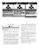
GAS PIPING CHECKS
CAUTION
T
O PREVENT PROPERTY DAMAGE OR PERSONAL INJURY DUE TO FIRE, THE
FOLLOWING INSTRUCTIONS MUST BE PERFORMED REGARDING GAS
CONNECTIONS AND PRESSURE TESTING:
•
T
HE UNIT AND ITS GAS CONNECTIONS MUST BE LEAK TESTED BEFORE
PLACING IN OPERATION.
B
ECAUSE OF THE DANGER OF EXPLOSION OR
FIRE, NEVER USE A MATCH OR OPEN FLAME TO TEST FOR LEAKS.
N
EVER
EXCEED SPECIFIED PRESSURES FOR TESTING.
H
IGHER PRESSURE MAY
DAMAGE GAS VALVE AND CAUSE OVERFIRING WHICH MAY RESULT IN
PREMATURE HEAT EXCHANGE FAILURE.
•
T
HIS UNIT AND ITS SHUT-OFF VALVE MUST BE DISCONNECTED FROM
THE GAS SUPPLY DURING ANY PRESSURE TESTING OF THAT SYSTEM AT
TEST PRESSURES IN EXCESS OF 1/2
PSIG
(3.48 K
P
A).
•
T
HIS UNIT MUST BE ISOLATED FROM THE GAS SUPPLY SYSTEM BY
CLOSING ITS MANUAL SHUT-OFF VALVE DURING ANY PRESSURE
TESTING OF THE GAS SUPPLY PIPING SYSTEM AT TEST PRESSURES
EQUAL TO OR LESS THAN 1/2
PSIG
(3.48 K
P
A).
WARNING
T
O AVOID PROPERTY DAMAGE OR PERSONAL INJURY, BE SURE THERE IS
NO OPEN FLAME IN THE VICINITY DURING AIR BLEEDING.
There will be air in the gas supply line after testing for leaks
on a new installation. Therefore, the air must be bled from the
line by loosening the ground joint union until pure gas is
expelled. Tighten union and wait for five minutes until all gas
has been dissipated in the air. Be certain there is no open
flame in the vicinity during air bleeding procedure. The unit is
placed in operation by closing the main electrical disconnect
switch for the unit.
PROPANE GAS INSTALLATIONS
WARNING
TO AVOID PROPERTY DAMAGE, PERSONAL INJURY OR DEATH DUE TO FIRE
OR EXPLOSION CAUSED BY A PROPANE GAS LEAK, INSTALL A GAS
DETECTING WARNING DEVICE.
S
INCE RUST CAN REDUCE THE LEVEL
OF ODORANT IN PROPANE GAS, A GAS DETECTING WARNING DEVICE
IS THE ONLY RELIABLE WAY TO DETECT A PROPANE GAS LEAK.
C
ONTACT A LOCAL PROPANE GAS SUPPLIER ABOUT INSTALLING A
GAS DETECTING WARNING DEVICE.
IMPORTANT NOTE: Propane gas conversion kits must be
installed to convert units to propane gas.
All propane gas equipment must conform to the safety
standards of the National Board of Fire Underwriters (See NBFU
Manual 58).
For satisfactory operation, propane gas supply pressure must
be within 9.7 - 10.3 inches W.C. at the manifold with all gas
appliances in operation. Maintaining proper gas pressure
depends on three main factors:
1. Vaporization rate, which depends on (a) temperature of the
liquid, and (b) wetted surface area of the container or
containers.
2. Proper pressure regulation.
3. Pressure drop in lines between regulators, and between
second stage regulator and the appliance. Pipe size
required will depend on length of pipe run and total load of
all appliances.