
GPG14M Installation Manual

9
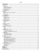
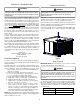
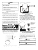
Thermostat Wiring - Two Stage Models
R
CW1W2
GY1Y2
R
Y2
CY1
W1
G
W2
Furnace Integrated
Control Module
Thermostat
Two-Stage Heating
with
Two-Stage Cooling
(
(
Two-Stage Heating with Two-Stage Cooling
Thermostat Diagram
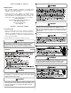
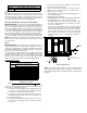
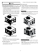
SINGLE STAGE THERMOSTAT - TWO-STAGE MODELS
To use a single stage thermostat, move jumper located to the
left of the terminal strip labeled “Stage Delay” from NONE to
“5” or “10” minutes. This selection will cause the control to
run on low stage for the selected time (5 or 10 minutes) then
shift to HIGH STAGE. This option controls both cooling and
heating modes. If the jumper is not moved, only low-stage
cool and low-stage heat will operate.
5 MINUTE DELAY
PERIOD WITH
JUMPER IN THIS
POSITION
10 MINUTE DELAY
PERIOD WITH
JUMPER IN THIS
POSITION
Two-Stage Heating (timed) and Two-Stage Cooling (timed)
with Single Stage Thermostat Diagram
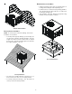
Refer to the unit wiring diagram for electrical connections.
When installed, the unit must be electrically grounded in
accordance with local codes or in the absence of local codes,
with the National Electrical Code, ANSI/NFPA No. 70, and/or
the CSA C22.1 Electrical Code. Ensure low voltage
connections are waterproof.
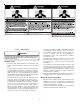
WARNING
T
O AVOID THE RISK OF ELECTRICAL SHOCK, WIRING TO THE UNIT MUST BE
POLARIZED AND GROUNDED.
CAUTION
T
O AVOID PROPERTY DAMAGE OR PERSONAL INJURY DUE TO FIRE, USE
ONLY COPPER CONDUCTORS.
WARNING
T
O PREVENT PROPERTY DAMAGE OR SERIOUS PERSONAL INJURY DUE TO
FIRE OR EXPLOSION CAUSED BY A PROPANE GAS LEAK, INSTALL A GAS
DETECTING WARNING DEVICE.
I
F THE PROPANE GAS UNIT IS INSTALLED IN AN EXCAVATED AREA OR A
CONFINED SPACE, A WARNING DEVICE IS REQUIRED DUE TO:
•
P
ROPANE GAS IS HEAVIER THAN AIR AND ANY LEAKING GAS CAN
SETTLE IN ANY LOW AREAS OR CONFINED SPACES.
•
P
ROPANE GAS ODORANT MAY FADE, MAKING THE GAS UNDETECTABLE
EXCEPT WITH A WARNING DEVICE.
ELECTRICAL WIRING
THERMOSTAT L OCATION
Mount the thermostat approximately five feet above the floor,
in an area that has an inside, vibration-free wall and has good
air circulation.
Movement of air must not be obstructed by furniture, door,
draperies, etc. The thermostat must not be mounted where it
will be affected by drafts, hot or cold water pipes or air ducts in
walls, radiant heat from fireplace, lamps, the sun, television,
etc. Consult the Instruction Sheet packaged with thermostat
for mounting instructions.
Five ton models have two stages of heating and two stages of
mechanical cooling. Units which have economizers may use
thermostats with two or three stages of cooling.
All other units have one stage of heating and one stage of
mechanical cooling. Units which have economizers may use
thermostats with one or two stages of cooling.
The units are designed for operation on 60 hertz current and
at voltages as shown on the rating plate. All internal wiring in
the unit is complete. It is necessary to bring in the power supply
to the contactor as shown on the unit wiring diagram which is
supplied with each unit. 24 volt wiring must be connected
between the unit control panel and the room thermostat.
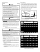
Thermostat Wiring - Single Stage Models
From
Unit
Single Stage Heating & Cooling Thermostat Diagram