
HKR Supplemental Install Instructions

2
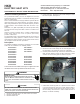
Figure 3
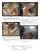
8. For single phase HKR kits only, mount the breaker (or termi-
nal block) to the rear mounting plate using the 4 blunt tip screws
included in the unit literature bag. The screw heads should all
be located on the outside of the mounting plate as shown in
Figure 4.
Figure 4
9. Locate the 9-pin harness in the unit and remove the male plug.
10. Connect the 9-pin plug from the unit to the 9-pin plug in the
heater kit.
11. Feed 9-pin harness wires through the rubber grommet, and
feed HKR wires through the plastic bushing in the rear mount-
ing plate. See Figure 5.
Figure 5
12. Install rear mounting plate with the 2 screws removed in step
6.
13. Connect the line voltage leads to the breaker(s), terminal block,
or contactor as applicable.
14. If heat kit includes breakers, remove rectangular knockout(s)
from outside cover as required for access.
15. Install the cover with the 2 screws removed in step 4, routing
the line voltage wires through the rubber grommet as shown
in Figure 6.
Figure 6
16. Install control box door and blower door.
17. Reconnect power and test.
Visit our websites at www.goodmanmfg.com or amana-hac.com for information on:
• Products • Parts
• Warranties • Contractor Programs and Training
• Customer Services • Financing Options
© 2006-2008 Goodman Manufacturing Company, L.P.
SHORT
SCREWS
Î
Î
LINE
VOLTAGE
Î
Î
HKR
WIRES
THROUGH
PLASTIC
BUSHING
Î
HARNESS WIRES
THROUGH
RUBBER GROMMET
AIR FLOW
DIRECTION
LABEL
Î