Service Instructions *PH 14 SEER PACKAGE HEAT PUMPS *PC 14 SEER PACKAGE COOLING MULTI-POSITION MODELS WITH R-410A REFRIGERANT Model numbers on page 6. This manual is to be used by qualified, professionally trained HVAC technicians only. Goodman does not assume any responsibility for property damage or personal injury due to improper service procedures or services performed by an unqualified person. RS6300013r2 September 2016 © 2014-2016 Goodman Manufacturing Company, L.P.
INDEX IMPORTANT INFORMATION ....................................................................................................... 4-5 PRODUCT IDENTIFICATION ....................................................................................................... 6-7 ACCESSORIES ............................................................................................................................... 8 GPGHFR101-103 .........................................................................................
INDEX S-17D Operation Test ............................................................................................................................... 29 S-18 TESTING CRANKCASE HEATER ................................................................................................................... 29 S-18A TESTING CRANKCASE HEATER THERMOSTAT ............................................................................ 29 S-21 CHECKING REVERSING VALVE AND SOLENOID ........................................
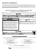
IMPORTANT INFORMATION Pride and workmanship go into every product to provide our customers with quality products. It is possible, however, that during its lifetime a product may require service. Products should be serviced only by a qualified service technician who is familiar with the safety procedures required in the repair and who is equipped with the proper tools, parts, testing instruments and the appropriate service manual.
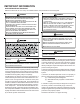
IMPORTANT INFORMATION SAFE REFRIGERANT HANDLING While these items will not cover every conceivable situation, they should serve as a useful guide. WARNING WARNING TO AVOID POSSIBLE EXPLOSION: • NEVER APPLY FLAME OR STEAM TO A REFRIGERANT CYLINDER. IF YOU REFRIGERANTS ARE HEAVIER THAN AIR. THEY CAN "PUSH OUT" THE T O AVOID OXYGEN IN YOUR LUNGS OR IN ANY ENCLOSED SPACE.
PRODUCT IDENTIFICATION The model number is used for positive identification of component parts used in manufacturing. Please use this number when requesting service or parts information.
PRODUCT IDENTIFICATION Single Phase Multiposition Cooling Model # Description APC14[24-60]M41AA Amana® Brand Package Cooling 14 SEER R410A Multiposition cooling units. Initial release of single phase models. GPC14[24-60]M41AA Goodman® Brand Package Cooling 14 SEER R410A Multiposition cooling units. Initial release of single phase models. APC14[24-60]M41AB Amana® Brand Package Cooling 14 SEER R410A Multiposition cooling units. Release of models with access box removed.
*PH/*PC14[24-60]M41* ACCESSORIES ACCESSORIES - *PC/*PH14**M MODELS Part Number Description OT18-60A Outdoor Thermostat Kit w/Lockout Stat OT/EHR18-60 Emergency Heat Relay Kit HKP[05,10,15,20]; HKR08 Single Phase 208-230 Volt Electric Heat Kit HKR3 Three Phase 208-230 Volt Electric Heat Kit PGC101/102/103 Roof Curb DHZECNJPGCHM Goodman/Daikin Horizontal Jade Economizer M Series Package Unit All Fuels, Medium Chassis, H Series All Fuels, All Chassis DHZECNJPGCHL Goodman/Daikin Horizontal Jade
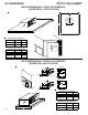
*PH/*PC14[24-60]M41* ACCESSORIES EXTERNAL HORIZONTAL FILTER RACK (GPGHFR101-103) 16" 24" 4" 16" x 25" x 2" FILTER 26 1/2" 17 1/4" Filter Size: 16" x 25" x 2" (Requires 1 filter) Measurement in inches DOWNFLOW FILTER RACK (GPH13MFR) PANEL SIDE VIEW DUCT SIDE VIEW FILTER PLATFORM LEFT SIDE RIGHT SIDE DOWNFLOW R/A DUCT OPENING EVAPORATOR COIL Filter Size: 14" x 25" x 2" (Requires 2 filters) - Measurement in inches 9
ACCESSORIES *PH/*PC14[24-60]M41* MOTORIZED/MANUAL FRESH AIR DAMPERS (HORIZONTAL APPLICATIONS) B 7 5/8 5 3/4 11 7/8 A B A Manual Fresh Air Dampers MODEL A B PGMDH102 31 1/2 29 3/4 PGMDH103 39 29 3/4 Motorized Fresh Air Dampers MODEL A B PGMDMH102 31 1/2 29 3/4 PGMDMH103 39 29 3/4 MOTORIZED/MANUAL FRESH AIR DAMPERS (DOWNFLOW APPLICATIONS) BOTTOM VIEW 12 1/8 6 5 3/4 10 11 7/8 1 PGMDD103 BOTTOM VIEW 12 1/8 10 5 3/4 6 11 7/8 1 PGMDD101/102 Manual Fresh Air Dampers MODEL A B PGMDD10
ACCESSORIES *PH/*PC14[24-60]M41* SQUARE TO ROUND CONVERTER (DOWNFLOW APPLICATIONS) 12 1/4 14 3/4 C D S 16 ø 22 3/4 16 ø 22 1/4 R A 12 1/4 14 3/4 B 22 3/4 22 1/4 18 ø 18 ø MODEL A B C D RETURN SUPPLY SQRPG101/102 22 3/4 12 1/4 22 1/4 14 3/4 16 16 SQRPG103 22 3/4 12 1/4 22 1/4 14 3/4 18 18 SQUARE TO ROUND CONVERTER (HORIZONTAL APPLICATIONS) B C MODEL A B C SQRPGH101/102 16 16 1/2 16 1/2 SQRP GH103 18 18 1/2 18 1/2 A Measurements are in inches.
ACCESSORIES *PH/*PC14[24-60]M41* ECONOMIZER GPJMED102 (DOWNFLOW APPLICATIONS) E C D F B PGED101/102 A B C D E F 20 16.25 16 23.5 12.5 45.
*PH/*PC14[24-60]M41* ACCESSORIES ECONOMIZER DHZECNJPGCH[M/L] (HORIZONTAL APPLICATIONS) B 16 1/8 18 D A E C MODEL A B C DHZECNJPGCHM 25 1/4 18 18 DHZECNJPGCHL 35 1/4 18 1/8 D E FILTER 18 13 3/4 16 1/8 16 X 25 X1 18 18 1/4 16 1/8 16 X 25 X1 Measurements in inches ROOF CURBS B S A R C 1 5/8 14 1/2 1 3/8 MODEL A B C RETURN SUPPLY PGC101/102/103 46 1/4* 39 3/8* 14 1/2 12 1/2 x 23* 15 x 22 1/2* *Inside Dimensions 13
PRODUCT DESIGN LOCATION & CLEARANCES NOTE: To ensure proper condensate drainage, unit must be installed in a level position. In installations where the unit is installed above ground level and not serviceable from the ground (Example: Roof Top installations) the installer must provide a service platform for the service person with rails or guards in accordance with local codes or ordinances.
PRODUCT DESIGN Air for condensing (cooling) is drawn through the outdoor coil by a propeller fan, and is discharged vertically out the top of the unit. The outdoor coil is designed for .0 static. No additional restriction (ductwork) shall be applied. Conditioned air is drawn through the filter(s), field installed, across the evaporator coil and back into the conditioned space by the indoor blower.
PRODUCT DESIGN WARNING TO AVOID THE RISK OF PROPERTY DAMAGE, PERSONAL INJURY OR FIRE, USE ONLY COPPER CONDUCTORS. LINE VOLTAGE WIRING Power supply to the unit must be N.E.C. Class 1, and must comply with all applicable codes. The unit must be electrically grounded in accordance with the local codes or, in their absence, with the latest edition of the National Electrical Code, ANSI/NFPA No. 70, or in Canada, Canadian Electrical Code, C22.1, Part 1.
SYSTEM OPERATION COOLING The refrigerant used in the system is R-410A. It is a clear, colorless, non-toxic and non-irritating liquid. R-410A is a 50:50 blend of R-32 and R-125. The boiling point at atmospheric pressure is -62.9°F.
SYSTEM OPERATION *PC/*PH14[24-60]M41* When auxiliary electric heaters are used, a two stage heating single stage cooling thermostat would be installed. frost cycle is not terminated due to the sensor temperature, a twelve minute override interrupts the unit’s defrost period. Should the second stage heating contacts in the room thermostat close, which would be wired to W1 at the unit low voltage connections, this would energize the coil(s) of the electric heat contactor(s)/sequencer(s) .
SYSTEM OPERATION Typical Heat Pump System in Cooling Reversing Valve (Energized) Indoor Coil Outdoor Coil Accumulator Typical Heat Pump System in Heating Reversing Valve (De-Energized) Outdoor Coil Indoor Coil Accumulator 19
SCHEDULED MAINTENANCE Package heat pumps require regularly scheduled maintenance to preserve high performance standards, prolong the service life of the equipment, and lessen the chances of costly failure. In many instances the owner may be able to perform some of the maintenance; however, the advantage of a service contract, which places all maintenance in the hands of a trained serviceman, should be pointed out to the owner. WARNING 6. Check the contacts of the compressor contactor.
SERVICING COOLING /HEAT PUMP- SERVICE ANALYSIS GUIDE Pow er Failure Blow n Fuse • • Shorted or Broken Wires • • • • Open Fan Overload Faulty Thermostat Faulty Transformer Shorted or Open Capacitor Internal Compressor Overload Open Shorted or Grounded Compressor Compressor Stuck • • • • • • • • • • • • • ♦ • • • • • ♦ • • • • • • Shorted or Grounded Fan Motor • • • Improper Cooling Anticipator Shortage of Refrigerant Restricted Liquid Line Open Element or Limit on Elec.
SERVICING S-1 CHECKING VOLTAGE WARNING Three phase units require a balanced 3 phase power supply to operate. If the percentage of voltage imbalance exceeds 3% the unit must not be operated until the voltage condition is corrected. Max. Voltage Deviation From Average Voltage X 100 Average Voltage % Voltage = Imbalance To find the percentage of imbalance, measure the incoming power supply. L1 - L2 = 240V Avg. V = 710 = 236.7 L1 - L3 = 232V 1. Remove doors, control panel cover, etc.
SERVICING S-2 CHECKING WIRING WARNING 5. No voltage, indicates the trouble is in the thermostat or wiring. 6. Check the continuity of the thermostat and wiring. Repair or replace as necessary. S-3B COOLING ANTICIPATOR The cooling anticipator is a small heater (resistor) in the thermostat. During the "off" cycle it heats the bimetal element helping the thermostat call for the next cooling cycle. This prevents the room temperature from rising too high before the system is restarted.
SERVICING S-4 CHECKING TRANSFORMER AND CONTROL CIRCUIT A step-down transformer (208/240 volt primary to 24 volt secondary) is provided with each package unit. This allows ample capacity for use with resistance heaters. S-8 CHECKING CONTACTOR CONTACTS WARNING DISCONNECT POWER SUPPLY BEFORE SERVICING. SINGLE PHASE WARNING 1. Disconnect the wire leads from the terminal (T) side of the contactor. 2. With power ON, energize the contactor. WARNING LINE VOLTAGE NOW PRESENT. 1.
SERVICING T3 T2 T1 4. Start the system and place a piece of cardboard in front of the condenser coil, raising the condensing pressure. 5. Check pressure at which the high pressure control cutsout.
SERVICING These capacitors have a 15,000 ohm, 2 watt resistor wired across its terminals. The object of the resistor is to discharge the capacitor under certain operating conditions, rather than having it discharge across the closing of the contacts within the switching device such as the Start Relay, and to reduce the chance of shock to the servicer. See the Servicing Section for specific information concerning capacitors.
SERVICING S-16D CHECKING EEM (ENERGY EFFICIENT MOTOR) MOTORS The EEM Motor is a one piece, fully encapsulated, 3 phase brushless DC (single phase AC input) motor with ball bearing construction. The EEM features an integral control module. Note: The GE TECMate will not operate the currently used EEM motor. 1. Using a voltmeter, check for 230 volts to the motor connections L and N. If 230 volts is present, proceed to step 2. If 230 volts is not present, check the line voltage circuit to the motor. 2.
SERVICING S-17A RESISTANCE TEST S-17B GROUND TEST Each compressor is equipped with an internal overload. If fuse, circuit breaker, ground fault protective device, etc., has tripped, this is a strong indication that an electrical problem exists and must be found and corrected. The circuit protective device rating must be checked and its maximum rating should coincide with that marked on the equipment nameplate. The line break internal overload senses both motor amperage and winding temperature.
SERVICING S-17D OPERATION TEST S-18 TESTING CRANKCASE HEATER If the voltage, capacitor, overload and motor winding test fail to show the cause for failure: Note: Not all compressors use crankcase heaters. The crankcase heater must be energized a minimum of twentyfour (24) hours before the compressor is operated. WARNING Crankcase heaters are used to prevent migration or accumulation of refrigerant in the compressor crankcase during the off cycles and prevents liquid slugging or oil pumping on start up.
SERVICING S-21 CHECKING REVERSING VALVE AND SOLENOID 7. Using VOM check for voltage across "W" & "C" terminals on the board. You should read 24 volts. Occasionally the reversing valve may stick in the heating or cooling position or in the mid-position. 8. If not as above, replace control board. When stuck in the mid-position, part of the discharge gas from the compressor is directed back to the suction side, resulting in excessively high suction pressure.
SERVICING S-52 CHECKING HEATER ELEMENTS Optional electric heaters may be added, in the quantities shown in the spec sheet for each model unit, to provide electric resistance heating. Under no condition shall more heaters than the quantity shown be installed. WARNING 4. Clean the inside of all new tubing to remove oils and pipe chips. 5. When brazing, sweep the tubing with dry nitrogen to prevent the formation of oxides on the inside surfaces. 6.
SERVICING S-102 EVACUATION WARNING REFRIGERANT UNDER PRESSURE! FAILURE TO FOLLOW PROPER PROCEDURES MAY CAUSE PROPERTY DAMAGE, PERSONAL INJURY OR DEATH. LOW SIDE GAUGE AND VALVE 800 PSI RATED HOSES CHARGING CYLINDER AND SCALE This is the most important part of the entire service procedure. The life and efficiency of the equipment is dependent upon the thoroughness exercised by the serviceman when evacuating air (non-condensable) and moisture from the system.
SERVICING S-103 CHARGING WARNING Final Charge Adjustment The outdoor temperature must be 60°F or higher. Set the room thermostat to COOL, fan switch to AUTO, and set the temperature control well below room temperature. After system has stabilized per startup instructions, compare the operating pressures and outdoor unit amp draw to the numbers listed in the technical manual. If pressures and amp draw are too low, add charge. If pressures and amp draw are too high, remove charge.
SERVICING S-105 THERMOSTATIC EXPANSION VALVE S-107 UNDERFEEDING The expansion valve is designed to control the rate of liquid refrigerant flow into an evaporator coil in exact proportion to the rate of evaporation of the refrigerant in the coil. The amount of refrigerant entering the coil is regulated since the valve responds to temperature of the refrigerant gas leaving the coil (feeler bulb contact) and the pressure of the refrigerant in the coil.
SERVICING SUPERHEAT AND SUBCOOLING ADJUSTMENT ON TXV APPLICATIONS SATURATED LIQUID PRESSURE TEMPERATURE CHART Single Speed Application (*PC1460) Liquid Pressure PSIG 200 210 220 225 235 245 255 265 275 285 295 305 325 355 375 405 1. Purge gauge lines. Connect service gauge manifold to access fittings. Run system at least 10 minutes to allow pressure to stabilize. 2.
SERVICING Pressure vs. Temperature Chart R-410A PSIG 12 14 16 18 20 22 24 26 28 30 32 34 36 38 40 42 44 46 48 50 52 54 56 58 60 62 64 66 68 70 72 74 76 78 80 82 84 86 88 90 92 94 96 98 100 102 104 106 108 110 112 °F -37.7 -34.7 -32.0 -29.4 -36.9 -24.5 -22.2 -20.0 -17.9 -15.8 -13.8 -11.9 -10.1 -8.3 -6.5 -4.5 -3.2 -1.6 0.0 1.5 3.0 4.5 5.9 7.3 8.6 10.0 11.3 12.6 13.8 15.1 16.3 17.5 18.7 19.8 21.0 22.1 23.2 24.3 25.4 26.4 27.4 28.5 29.5 30.5 31.2 32.2 33.2 34.1 35.1 35.5 36.9 PSIG 114.0 116.0 118.0 120.0 122.
SERVICING REQUIRED LIQUID LINE TEMPERATURE LIQUID PRESSURE AT SERVICE VALVE (PSIG) 189 195 202 208 215 222 229 236 243 251 259 266 274 283 291 299 308 317 326 335 345 354 364 374 384 395 406 416 427 439 450 462 474 486 499 511 8 58 60 62 64 66 68 70 72 74 76 78 80 82 84 86 88 90 92 94 96 98 100 102 104 106 108 110 112 114 116 118 120 122 124 126 128 REQUIRED SUBCOOLING TEMPERATURE (°F) 10 12 14 16 56 54 52 50 58 56 54 52 60 58 56 54 62 60 58 56 64 62 60 58 66 64 62 60 68 66 64 62 70 68 66 64 72 70 68 66 7
SERVICING NOTE: To adjust superheat, turn the valve stem clockwise to increase and counter clockwise to decrease. b. If subcooling is low and superheat is high, add charge to raise subcooling to 5 to 7 ºF then check superheat. c. If subcooling and superheat are high, adjust TXV valve to 15 to 18ºF superheat, then check subcooling. d. If subcooling is high and superheat is low, adjust TXV valve to 15 to 18ºF superheat and remove charge to lower the subcooling to 5 to 7 ºF.
SERVICING S-114 NON-CONDENSABLES Check for non-condensables. 1. Shut down the system and allow the pressures to equalize for a minimum of 15 minutes. 2. Take a pressure reading. 3. Compare this pressure to the temperature of the coldest coil since this is where most of the refrigerant will be. If the pressure indicates a higher temperature than that of the coil temperature, non-condensables are present. To remove the non-condensables. 1. Remove the refrigerant charge. 2.
SERVICING S-200 CHECKING EXTERNAL STATIC PRESSURE Temperature rise is related to the BTUH output of the unit and the amount of air (CFM) circulated over the indoor coil. The minimum and maximum allowable duct static pressure is found in the Technical Information Manual. All units are designed for a given range of temperature increase. This is the temperature of the air leaving the unit minus the temperature of the air entering the unit.
WIRING DIAGRAMS PACKAGE SYSTEM WIRING DIAGRAM - 1 STAGE ELECTRIC HEAT TYPICAL HP ROOM THERMOSTAT SEE NOTE 1 #18 GAUGE 7 WIRE REQUIRED FOR HEAT PUMPS Y O C W1 G R PACKAGE UNIT LOW VOLTAGE JUNCTION BOX E R R RED Y Y YELLOW G G GREEN O O ORANGE BR W WHITE BL BLUE HIGH VOLTAGE! DISCONNECT ALL POWER BEFORE SERVICING OR INSTALLING THIS UNIT. MULTIPLE POWER SOURCES MAY BE PRESENT. FAILURE TO DO SO MAY CAUSE PROPERTY DAMAGE, PERSONAL INJURY OR DEATH.
WIRING DIAGRAMS PACKAGE SYSTEM WIRING DIAGRAM - HEAT PUMPS ONLY! TWO-STAGE ELECTRIC HEAT ABOVE 10 kW TYPICAL H/P ROOM THERMOSTAT W2 Y O C W1 G R #18 GAUGE 8 WIRE E HIGH VOLTAGE! DISCONNECT ALL POWER BEFORE SERVICING OR INSTALLING THIS UNIT. MULTIPLE POWER SOURCES MAY BE PRESENT. FAILURE TO DO SO MAY CAUSE PROPERTY DAMAGE, PERSONAL INJURY OR DEATH.
WIRING DIAGRAMS FL FL FL HTR1 TL HTR1 TL PLM BK BK PLM BK 2 PU BL M1 4 M2 5 W BK R HIGH VOLTAGE! DISCONNECT ALL POWER BEFORE SERVICING OR INSTALLING THIS UNIT. MULTIPLE POWER SOURCES MAY BE PRESENT. FAILURE TO DO SO MAY CAUSE PROPERTY DAMAGE, PERSONAL INJURY OR DEATH.
CIRCUIT 2 3 PH. 208-240V HIGH VOLTAGE! DISCONNECT ALL POWER BEFORE SERVICING OR INSTALLING THIS UNIT. MULTIPLE POWER SOURCES MAY BE PRESENT. FAILURE TO DO SO MAY CAUSE PROPERTY DAMAGE, PERSONAL INJURY OR DEATH. B17579-19 WIRING DIAGRAMS 3-PHASE HKR** HEAT KIT - 15 KW & 20 KW Wiring is subject to change. Always refer to the wiring diagram on the unit for the most up-to-date wiring.
+ COM 3 2 1 (O) ORANGE O R (G) GREEN (O) ORANGE (R) RED 6 8 5 4 8 7 1 2 3 WHITE RED BLACK Y1 TSTAT Y2 TSTAT Y/Y2 (CONTACTOR)(CC2) COMMON Y1 (CONTACTOR) (CC1) 6 9 G WIRE LENGTHS FOR PLUG 2 PURPLE = 2 X 77" YELLOW = 2 X 77" BLUE = 1 X 77" GREEN = 1 X 77" 9 (Y) YELLOW (BL) BLUE (P) PURPLE 3 5 (P) PURPLE 2 4 (Y) YELLOW 1 COLOR CODES FOR PLUG 2 WIRE LENGTHS FOR PLUG 1 ORANGE = 1 X 78" GROUND = 1 X 50" GROUND (G)GREEN 8 COLOR CODES FOR PLUG 1 2...
WIRING DIAGRAMS *PC14[24-60]M41A* HIGH VOLTAGE! DISCONNECT ALL POWER BEFORE SERVICING OR INSTALLING THIS UNIT. MULTIPLE POWER SOURCES MAY BE PRESENT. FAILURE TO DO SO MAY CAUSE PROPERTY DAMAGE, PERSONAL INJURY OR DEATH.
WIRING DIAGRAMS *PH14[24-48]M41A* HIGH VOLTAGE! DISCONNECT ALL POWER BEFORE SERVICING OR INSTALLING THIS UNIT. MULTIPLE POWER SOURCES MAY BE PRESENT. FAILURE TO DO SO MAY CAUSE PROPERTY DAMAGE, PERSONAL INJURY OR DEATH.
WIRING DIAGRAMS *PH1460M41A* HIGH VOLTAGE! DISCONNECT ALL POWER BEFORE SERVICING OR INSTALLING THIS UNIT. MULTIPLE POWER SOURCES MAY BE PRESENT. FAILURE TO DO SO MAY CAUSE PROPERTY DAMAGE, PERSONAL INJURY OR DEATH.