
Service Manual

SYSTEM OPERATION
17
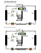
COOLING
The refrigerant used in the system is R-410A. It is a clear,
colorless, non-toxic and non-irritating liquid. R-410A is a 50:50
blend of R-32 and R-125. The boiling point at atmospheric
pressure is -62.9°F.
A few of the important principles that make the refrigeration
cycle possible are: heat always flows from a warmer to a
cooler body, under lower pressure a refrigerant will absorb
heat and vaporize at a low temperature, the vapors may be
drawn off and condensed at a higher pressure and tempera-
ture to be used again.
The indoor evaporator coil functions to cool and dehumidify
the air conditioned spaces through the evaporative process
taking place within the coil tubes.
NOTE: Actual temperatures and pressures are to be obtained
from the expanded ratings in the Technical Information
Manual.
High temperature, high pressure vapor leaves the compres-
sor through the discharge line and enters the condenser coil.
Air drawn through the condenser coil by the condenser fan
causes the refrigerant to condense into a liquid by removing
heat from the refrigerant. As the refrigerant is cooled below
its condensing temperature it becomes subcooled.
The subcooled high pressure liquid refrigerant now leaves the
condenser coil via the liquid line until it reaches the indoor
expansion device.
As the refrigerant passes through the expansion device and
into the evaporator coil a pressure drop is experienced caus-
ing the refrigerant to become a low pressure liquid. Low pres-
sure saturated refrigerant enters the evaporator coil where
heat is absorbed from the warm air drawn across the coil by
the evaporator blower. As the refrigerant passes through the
last tubes of the evaporator coil it becomes superheated,
that is, it absorbs more heat than is necessary for the refrig-
erant to vaporize. Maintaining proper superheat assures that
liquid refrigerant is not returning to the compressor which
can lead to early compressor failure.
Low pressure superheated vapor leaves the evaporator coil
and returns through the suction line to the compressor where
the cycle begins again.
COOLING CYCLE
Cooling Only Models
When the contacts of the room thermostat close, making
terminals R to Y and R to G, the low voltage circuit to the
contactor is completed starting the compressor and outdoor
fan motor. The EEM indoor blower motor is energized at the
cool speed when the compressor contactor energizes.
When the thermostat is satisfied, breaking the circuit be-
tween R to Y and R to G, the compressor and outdoor fan
motor will stop. The indoor blower will stop after the fan off
delay.
If the room thermostat fan selector switch should be set to
the "on" position then the indoor blower would run continu-
ous rather than cycling with the compressor.
Heat Pump Models
Any time the room thermostat is switched to cool, the O
terminal is energized. This energizes the 24 volt coil on the
reversing valve and switches it to the cooling position.
When the contacts of the room thermostat close, this closes
the circuit from R to Y and R to G in the unit.
This energizes the compressor contactor and will energize
the indoor blower on models equipped with the EEM motor.
When the thermostat is satisfied, it opens its contacts break-
ing the low voltage circuit causing the compressor contactor
to open and indoor fan to stop after the programmed 60 sec-
ond off delay on units with the EEM motor.
If the room thermostat fan selector switch should be set to
the "on" position then the indoor blower would run continu-
ous rather than cycling with the compressor.
HEATING CYCLE
Cooling Only Units
NOTE: The following only applies if the cooling only unit has
an approved electric heat kit installed for heating. If auxiliary
electric heaters should be used, they may be controlled by
outdoor thermostats (OT18-60A or OT/EHR18-60A).
*PC EEM Equipped Model Units
With the thermostat set to the heat position and a call for
heat, R to W will be energized. This will energize the electric
heat contactor(s)/sequencer(s) and the EEM indoor blower
motor. When the normally open contacts of the heat
contactor(s)/sequencer(s) close, this will energize the
electric resistance heat.
*PH14**M41* Heat Pump Units
On a call for first stage heat, the contacts of the room ther-
mostat close. This energizes terminals R to Y and R to G,
the low voltage circuit to the contactor is completed starting
the compressor and outdoor fan motor. This also energizes
the indoor blower on models equipped with the EEM motor.
When the thermostat is satisfied, breaking the circuit be-
tween R to Y and R to G, the compressor and outdoor fan
motor will stop. The indoor blower will stop after the pro-
grammed 60 second off delay on models equipped with the
EEM motor.
*PC/*PH14[24-60]M41*