
Service Manual


SERVICING
38
NOTE: To adjust superheat, turn the valve stem
clockwise to increase and counter clockwise to de-
crease.
b. If subcooling is low and superheat is high, add charge
to raise subcooling to 5 to 7 ºF then check super-
heat.
c. If subcooling and superheat are high, adjust TXV
valve to 15 to 18ºF superheat, then check subcooling.
d. If subcooling is high and superheat is low, adjust
TXV valve to 15 to 18ºF superheat and remove
charge to lower the subcooling to 5 to 7 ºF.
NOTE: Do NOT adjust the charge based on suction pres-
sure unless there is a gross undercharge.
4. Disconnect manifold set, installation is complete.
SUBCOOLING = SAT. LIQUID TEMP. - LIQUID LINE TEMP.
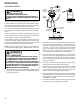
Heat Pump - Heating Cycle
The proper method of charging a heat pump in the heat mode
is by weighing the charge according to the total charge listed
on the rating plate.
S-109 CHECKING SUBCOOLING
Refrigerant liquid is considered subcooled when its tempera-
ture is lower than the saturation temperature corresponding to
its pressure. The degree of subcooling equals the degrees of
temperature decrease below the saturation temperature at the
existing pressure.
1. Attach an accurate thermometer or preferably a thermo-
couple type temperature tester to the liquid line close to
the high pressure access fitting process tube.
2. Install a high side pressure gauge on the high side (liquid)
access fitting.
3. Record the gauge pressure and the temperature of the line.
4. Review the technical information manual or specification
sheet for the model being serviced to obtain the design
subcooling.
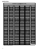
5. Compare the hi-pressure reading to the "Required Liquid
Line Temperature" chart . Find the hi-pressure value on the
left column. Follow that line right to the column under the
design subcooling value. Where the two intersect is the
required liquid line temperature.
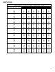
Alternately you can convert the liquid line pressure gauge
reading to temperature by finding the gauge reading in Tem-
perature - Pressure Chart and reading to the left, find the
temperature in the °F. Column.
6. The difference between the thermometer reading and pres-
sure to temperature conversion is the amount of subcooling.
Add charge to raise subcooling. Recover charge to lower
subcooling.
SUBCOOLING = SAT. LIQUID TEMP. - LIQUID LINE TEMP.
EXAMPLE:
a. Liquid Line Pressure = 417
b. Corresponding Temp. °F. = 120°
c. Thermometer on Liquid line = 113°F.
To obtain the amount of subcooling subtract 113°F from 120°F.
The difference is 7° subcooling, which would fall in the
+ range
of allowable subcooling.
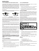
S-110 CHECKING EXPANSION VALVE
OPERATION
1. Remove the remote bulb of the expansion valve from the
suction line.
2. Start the system and cool the bulb in a container of ice
water, closing the valve. As you cool the bulb, the suction
pressure should fall and the suction temperature will rise.
3. Next warm the bulb in your hand. As you warm the bulb,
the suction pressure should rise and the suction tempera-
ture will fall.
4. If a temperature or pressure change is noticed, the expan-
sion valve is operating. If no change is noticed, the valve is
restricted, the power element is faulty, or the equalizer
tube is plugged.
5. Capture the charge, replace the valve and drier, evacuate
and recharge.
S-112 CHECKING RESTRICTED LIQUID LINE
When the system is operating, the liquid line is warm to the
touch. If the liquid line is restricted, a definite temperature
drop will be noticed at the point of restriction. In severe cases,
frost will form at the restriction and extend down the line in the
direction of the flow.
Discharge and suction pressures will be low, giving the ap-
pearance of an undercharged unit. However, the unit will have
normal to high subcooling.
If a restriction is located, replace the restricted part, replace
drier, evacuate and recharge.
S-113 REFRIGERANT OVERCHARGE
An overcharge of refrigerant is normally indicated by exces-
sively high head pressure and/or liquid return to the compres-
sor.
If high head pressure is not indicated, an overcharge or a sys-
tem containing non-condensables could be the problem.
If overcharging is indicated:
1. Start the system.
2. Remove small quantities of gas from the suction line dill
valve until the head pressure is reduced to normal.
3. Observe the system while running a cooling performance
test, if a shortage of refrigerant is indicated, then the sys-
tem contains non-condensables. See S-114 Non-
Condensables.