
Installation Guide


11
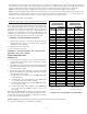
The leads are factory connected as follows: Green to T1, Yellow to T2, and White to T3. T1 is the low speed setting and
is dedicated to fan-only mode. T2 is medium speed cooling and T3 is medium speed heating. T4 is high speed cooling
and T5 is high speed heating. To adjust the blower speed, move the yellow and/or white wires to T4 and T5.
NOTE: If more than one lead is energized at the same time, the motor will use the higher speed setting.
NOTE: GPC15 and GPH16 units are rated for a maximum E.S.P. of 0.8 except when using a 20kw electric heater. (The
maximum static for 20 kW electric heat is 0.5 E.S.P.) When these units are installed in the 0.5 - 0.8 E.S.P. range, the
white lead (electric heat) must be moved to T5 for proper operation of the electric heaters.
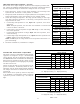
See CFM vs ESP tables in this manual.
Refrigerant Charge Check (Units with Fixed Orifice Devices)
After completing airflow measurements and adjustments the
unit’s refrigerant charge must be checked. All package units
with fixed orifice devices are charged using the super heat
method at the compressor suction line. After superheat is
adjusted it is recommended to check unit sub-cooling at the
condenser coil liquid line out. For charge adjustments, see
superheat and subcooling charts shown for each model.
SUPERHEAT CAN BE DETERMINED AS FOLLOWS:
1. Read suction pressure. Determine Saturated Suction
Temperature from tables or pressure gauge saturated
temperature scale (R-410A).
2. Read suction line temperature.
3. Use the following formula:
SUPERHEAT = SUCTION LINE TEMP - SAT. SUCTION TEMP.
EXPANSION VALVE (TXV) SYSTEM
SINGLE SPEED APPLICATION
(GPH1624-42)
1. Purge gauge lines. Connect service gauge manifold to
access fittings. Run system at least 10 minutes to allow
pressure to stabilize.
2. Temporarily install thermometer on liquid (small) line near
liquid line access fitting with adequate contact and insulate
for best possible reading.
3. Check subcooling and superheat. Systems with TXV
application should have a subcooling and superheat within
the range listed on the chart.
a. If subcooling and superheat are low, adjust TXV then
check subcooling.
b. If subcooling is low and superheat is high, add charge
to raise subcooling then check superheat.
c. If subcooling and superheat are high, adjust TXV valve
then check subcooling.
d. If subcooling is high and superheat is low, adjust TXV
valve superheat and remove charge to lower the
subcooling.
The TXV should NOT be adjusted at light load conditions 55º to
60ºF, under such conditions only the subcooling can be evalu-
ated. This is because suction pressure is dependent on indoor
air flow, and wet bulb temperature.
NOTE: Do NOT adjust charge based on suction pressure unless there is a gross undercharge.
4. Disconnect manifold set. Installation is complete.
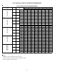
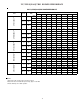
SUCTION
PRESSURE
SATURATED
SUCTION
TEMPERATURE
ºF
LIQUID
PRESSURE
SATURATED
LIQUID
TEMPERATURE
ºF
PSIG R-410A PSIG R-410A
50 1 200 70
52 3 210 73
54 4 220 76
56 6 225 78
58 7 235 80
60 8 245 83
62 10 255 85
64 11 265 88
66 13 275 90
68 14 285 92
70 15 295 95
72 16 305 97
74 17 325 101
76 19 355 108
78 20 375 112
80 21 405 118
85 24 415 119
90 26 425 121
95 29 435 123
100 31 445 125
110 36 475 130
120 41 500 134
130 45 525 138
140 49 550 142
150 53 575 145
160 56 600 149
170 60 625 152
SATURATED
SUCTION PRESSURE
TEMPERATURE CHART
SATURATED
LIQUID PRESSURE
TEMPERATURE CHART
TABLE 5
Suction Pressure Liquid Pressure
Temperature (R-410A) Temperature (R-410A)
SUBCOOLING = SAT. LINE TEMP - LIQUID LINE TEMP.