
Installation Guide


12
TWO SPEED APPLICATION (GPH1648 / GPC1560)
Run the unit on low stage cooling for 10 minutes until refrigerant pressures stabi-
lize. Follow the guidelines and methods below to check unit operation and ensure
that the refrigerant charge is within limits. Charge the unit on low stage.
1. Purge gauge lines. Connect service gauge manifold to access fittings. Run
system at least 10 minutes to allow pressure to stabilize.
2. Temporarily install thermometer on liquid (small) line near liquid line access
fitting with adequate contact and insulate for best possible reading.
3. Check subcooling and superheat. Two stage systems running on low stage
with TXV application should have a subcooling and superheat within the
range listed on the chart.
a. If subcooling and superheat are low, adjust TXV superheat, then check
subcooling.
NOTE: To adjust superheat, turn the valve stem clockwise to increase and
counter clockwise to decrease.
b. If subcooling is low and superheat is high, add charge to raise subcooling
then check superheat.
c. If subcooling and superheat are high, adjust TXV valve superheat, then
check subcooling.
d. If subcooling is high and superheat is low, adjust TXV valve superheat and
remove charge to lower the subcooling.
NOTE: Do NOT adjust the charge based on suction pressure unless there is a
gross undercharge.
4. Disconnect manifold set, installation is complete.
ELECTRIC HEAT INSTALLATION & ADJUSTMENT
This series of electric cooling and heat pump package
equipment is designed to accept a field installed
electric heat kit. The unit is equipped to easily install
the HKR/HKP Series Electric Heat Kit. Full Installation
Instructions are included in this kit. Please use this
document for guidance in field equipping the package
unit with electric heat.
Choose the heat kit that fits the application for the
specific installation. Permanently mark the unit’s
nameplate with the model being installed. High and
low voltage connections are detailed in the heat kit
instructions.
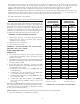
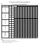
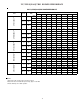
Indoor Blower motor speed tap selection may need
to be modified to accommodate normal continuous
operation to prevent a nuisance trip. See tables at
right.
5 8 10 15 20
GPC1524/GPH1624H41** T3 T3 T3 T5 NA
GPC1530/GPH1630H41** T3 T3 T3 T5 NA
GPC1536/GPH1636H41** T3 T3 T3 T5 NA
GPC1542/GPH1642H41** T3 T3 T3 T3 T5
GPC1548/GPH1648H41** T3 T3 T3 T3 T3
GPC1560H41** T3 T3 T3 T3 T3
Electric Heat KW
T1 - Fan Only; T2 - Normal Speed Cooling
T3 - Normal Speed Heating
T4 - High Speed Cooling; T5 - High Speed Heating
GPC15/GPH16(24-60) Models (0 - 0.5 E.S.P.)
Unit Model Number
5 8 10 15 20
GPC1524/GPH1624H41** T5 T5 T5 T5 NA
GPC1530/GPH1630H41** T5 T5 T5 T5 NA
GPC1536/GPH1636H41** T5 T5 T5 T5 NA
GPC1542/GPH1642H41** T5 T5 T5 T5 NA
GPC1548/GPH1648H41** T5 T5 T5 T5 NA
GPC1560H41** T5 T5 T5 T5 NA
GPC15/GPH16(24-60) Models (0 - 0.5 E.S.P.)
Unit Model Number
Electric Heat KW
T1 - Fan Only; T2 - Normal Speed Cooling
T3 - Normal Speed Heating
T4 - High Speed Cooling; T5 - High Speed Heating
TABLE 7A & 7B
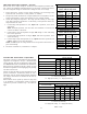
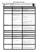
TABLE 6A & 6B
Model #
Superheat
± 2°F
Subcooling
± 2°F
GPC1524H41 6
°
---
GPC1530H41 8°
---
GPC1536H41 12°
---
GPC1542H41 7°
---
GPC1548H41 10°
---
GPC1560H41 12°
12°
GPC15
Design superheat @ 95 °F
outdoor ambient temperature
Model #
Superheat
± 2°F
Subcooling
± 2°F
GPH1624H41 15° 7°
GPH1630H41 15° 7°
GPH1636H41 10° 13°
GPH1642H41 12° 13°
GPH1648H41 15° 15°
GPH16
Design superheat @ 95 °F
outdoor ambient temperature