
Installation Guide

6
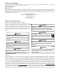
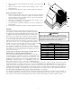
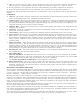
OUTER FLANGE
STARTER FLANGE
SQUARE TO ROUND
DUCT CONVERTER PANEL
FIGURE 3
Plenum Application
A suitable plenum or square duct must be constructed. The duct cross-sectional area should be determined by industry
duct sizing manuals or air duct calculators.
On ductwork exposed to outside air conditions of temperature and humidity, use an insulation with a good K factor, and
a vapor barrier. Industry practices should be followed. Balancing dampers are recommended for each branch duct in the
supply system. Ductwork should be properly supported from the unit.
NOTE: Proper sealing of all duct work and air handling compartments is extremely important to overall unit efficiency.
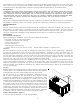
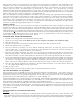
Filters
Filters are not provided with unit, and must be supplied and installed in the return duct system by the installer. A field
installed filter grille is recommended for easy and convenient access to the filters for periodic inspection and cleaning.
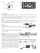
Filters must have adequate face area for the rated quantity of the
unit. See air delivery tables (Figure 4) for recommended filter size.
PIPING
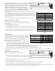
Condensate Drain
The condensate drain connection of the evaporator is a half coupling
of ¾” N.P.T. A trap must be provided to have Proper condensate
drainage.
Install condensate drain trap as shown. Use ¾ “ drain connection size
or larger. Do not operate without trap. Unit must be level or slightly
inclined toward drain.
WIRING
All wiring should be made in accordance with the National
Electrical Code. The local Power Company should be consulted
to determine the availability of sufficient power to operate
the unit. The voltage, frequency, and phase at the power
supply should be checked to make sure it corresponds to the unit’s RATED VOLTAGE REQUIREMENT.
Install a branch circuit fused disconnect near the unit, in
accordance with the N.E.C. or local codes. Wire sizes and
overcurrent protection should be determined from the unit
nameplate ampacity and in accordance with Table 4 (page
7) or the N.E.C. Under no circumstances should wiring be
sized smaller than is recommended by either of these two
sources.
Fuses smaller than that recommended on the wiring diagrams
could result in unnecessary fuse failure or service calls. The
use of protective devices of larger size than indicated could
result in extensive damage to the equipment. The
manufacturer bears no responsibility for damage caused to
equipment as result of the use of larger than is recommended
size protective devices.
500 1000 1500 2000 2500 3000 3500
7
6
5
4
3
2
D
I
S
P
O
S
A
B
L
E
F
I
L
T
E
R
P
E
R
M
A
N
E
N
T
F
I
L
T
E
R
Airflow - SCFM
N
o
m
i
n
a
l
F
i
l
t
e
r
A
r
e
a
S
q
u
a
r
e
F
e
e
t
FIGURE 4
2" Minimum
3" Minimum
A
Positive Liquid Seal
Is Required
Flexible
Tubing-Hose
Or Pipe
Drain
Connection
Unit
FIGURE 5
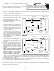
CONTACTOR
R
W
G
G
RW
FOR INTERNAL WIRING SEE WIRING LABEL ATTACHED TO UNIT
24 VOLT CONTROL WIRING
FIGURE 6