
Installation Guide

7
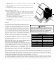
All units have undergone a run test prior to packaging for
shipment. This equipment has been started at minimum rated
voltage and checked for satisfactory operation. Do not
attempt to operate this unit if the voltage is not within the
minimum and maximum voltages shown on nameplate.
All exterior wiring must be within approved weatherproof
conduit. The unit must be permanently grounded in
accordance with local codes, or in absence of local codes,
with N.E.C ANSI/ NFPA NO. 70-1984 or latest edition by using ground lug in the
control box.
Fuses or HACR type circuit breakers may be used where codes permit.
Note: Some single phase units are equipped with a single pole contactor. Caution
must be exercised when servicing as only one leg of the power supply is broken
with the contactor.
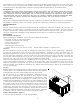
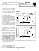
To wire the unit, make the following high and low voltage connections.
High Voltage Wiring: (See Figure 6)
Single Phase- Two leads should be connected to terminals L1
& L2 in the electrical control section, using wire sizes specified
in wiring table.
Low Voltage Wiring: (See Figure 6)
a. Air Conditioners- Connect 24V wires from the thermostat to the
corresponding wires in the control box using No. 18AWG as shown in TABLE
2.
b. Heat Pumps- Connect 24V wires from the thermostat to the corresponding
wires in the control box using No. 18AWG as shown in TABLE 3.
Internal Wiring:
A diagram detailing the internal wiring of this unit is located
on the electrical box cover. If any of the original wire supplied
with the appliance must be replaced, the wire gauge and
insulation must be the same as the original wiring.
Transformer is wired for 230 volts on the 208/230 models.
See wiring diagram for 208 volt wiring.
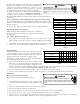
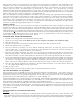
1. For branch circuit wiring (main power supply to unit
disconnect), the minimum wire size for the length of the
run can be determined from Table 4 using the circuit
ampacity found on the unit rating plate. From the unit disconnect to unit, the smallest wire size allowable in Table 4
may be used for the ampacity, as the Disconnect must be in sight of the unit.
2. Wire size based on 60° C rated wire insulation and 30° C Ambient Temperature (86° F).
3. For more than 3 conductors in a raceway or cable, see the N.E.C. for derating the ampacity of each conductor.
OPERATION
Start-Up Procedure and Checklist
Begin with power turned off at all disconnects.
1. Turn thermostat system switch to “Cool,” and fan switch
to “Auto” and turn temperature setting as high as it will
go.
2. Inspect all registers and set them to the normal open position.
3. Turn on the electrical supply at the disconnect.
4. Turn the fan switch to the “ON” position. The blower should operate after a 10 second delay.
5. Turn the fan switch to “Auto” position. The blower should stop after a 60 second delay.
6. Slowly lower the cooling temperature until the unit starts. The compressor, blower and fan should now be operating.
Allow the unit to run 10 minutes, make sure cool air is being supplied by the unit.
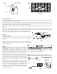
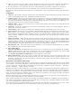
LEAD THERMOSTAT
Red R (24V)
Green G (Fan)
Yellow Y (Cool)
White W1 (Heat)*
Brown W2 (Heat)*
TERMINAL THERMOSTAT
Red R (24V)
Green G (Fan)
Orange O (Rev. Valve)
White W1 (Heat, 2nd)*
Brown W2 (Heat 3rd)*
Yellow Y (Cool)
C (Blue) C (Common)
TABLE 2
TABLE 3
*Optional field installed heat connections
BRANCH CIRCUIT AMPACITY
15 20 25 30 35 40 45 50
SUPPLY WIRE LENGTH -
FEET
200 64443322
150 86644433
100 108866644
50 14 12 10 10 8 8 6 6
TABLE 4
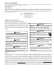
WARNING
HIGH
VOLTAGE
!
D
ISCONNECT
ALL
POWER BEFORE SERVICING OR INSTALLING
THIS UNIT.
M
ULTIPLE POWER SOURCES MAY BE PRESENT. FAILU
TO DO SO MAY CAUSE PROPERTY DAMAGE, PERSONAL INJURY O
DEATH.
RE
R
WARNING
HIGH
VOLTAGE
!
D
ISCONNECT
ALL
POWER BEFORE SERVICING OR INSTALLING
THIS UNIT.
M
ULTIPLE POWER SOURCES MAY BE PRESENT. FAILU
TO DO SO MAY CAUSE PROPERTY DAMAGE, PERSONAL INJURY O
DEATH.
RE
R