
Installation Guide

8
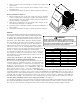
7. Turn the temperature setting to the highest position,
stopping the unit. The indoor blower will continue to run
for 60 seconds.
8. Turn the thermostat system switch to “OFF” and
disconnect all power when servicing the unit.
Heat Pump Start-Up Procedure
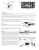
9. Check the cooling mode for the heat pump in the same manner as above. The reversing valve is energized when the
thermostat is placed in the cooling position.
A clicking sound should be noticeable from
the reversing valve. By lowering the
temperature setting to call for cooling, the
contractor is energized. The compressor,
blower and fan should then be running. After
the cooling mode is checked out, turn the
thermostat system switch to “OFF”.
10. Turn the thermostat system switch to “HEAT”
and fan switch to “AUTO”.
11. Slowly raise the heating temperature setting.
When the heating first stage makes contact,
stop raising the temperature setting.. The
compressor, blower and fan should now be
running with the reversing valve in the de-
energized (heating) position. After giving the
unit time to settle out, make sure the unit
is supplying heated air.
12. If the out door ambient is above 80°F, the
unit may trip on its high pressure cut out
when on heating. The compressor should
stop. The heating cycle must be thoroughly
checked, so postpone the test to another day
when conditions are more suitable but-DO
NOT FAIL TO TEST.
If the out door ambient is low and the unit
operates properly on the heating cycle, you
may check the pressure cutout operation by
blocking off the indoor return air until the
unit trips.
13. If unit operates properly in the heating cycle,
raise the temperature setting until the
heating second stage makes contact.
Supplemental resistance heat, if installed
should now come on. Make sure it operates
properly.
NOTE: If outdoor thermostats are installed
the outdoor ambient must be below the set
point of these thermostats for the heaters
to operate. It may be necessary to jumper
these thermostats to check heater
operation if outdoor ambient is mild.
14. For thermostats with emergency heat switch,
return to step 11. The emergency heat switch is located at the bottom of the thermostat. Move the switch to
emergency heat. The heat pump will stop, the blower will continue to run, all heaters will come on and the thermostat
emergency heat light will come on.
15. If checking the unit in the wintertime, when the outdoor coil is cold enough to actuate the defrost control, observe at
least one defrost cycle to make sure the unit defrosts completely.
Final System Checks
16. Check to see if all supply and return air grilles are adjusted and the air distribution system is balanced for the best
compromise between heating and cooling.
17. Check for air leaks in the ductwork.
18. See Sections on Air Flow Measurement and Adjustment and Checking Charge.
WARNING
HIGH
VOLTAGE
!
D
ISCONNECT
ALL
POWER BEFORE SERVICING OR INSTALLING
THIS UNIT.
M
ULTIPLE POWER SOURCES MAY BE PRESENT. FAILU
TO DO SO MAY CAUSE PROPERTY DAMAGE, PERSONAL INJURY O
DEATH.
RE
R
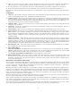
E
V
A
P
O
R
A
T
O
R
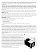
COOLING
SERVICE VALVE
SERVICE PORT
REVERSING VALVE
C
O
N
D
E
N
S
E
R
SERVICE PORT
COMPRESSOR
SERVICE PORT
ACCUMULATOR
EXPANSION DEVICE
CHECK VALVE
ORIFICE
SERVICE
VALVE
CHECK VALVE
ORIFICE
INDOOR
COIL
DISTRIBUTOR
OUTDOOR
COIL
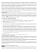
E
V
A
P
O
R
A
T
O
R
HEATING
SERVICE VALVE
SERVICE PORT
REVERSING VALVE
C
O
N
D
E
N
S
E
R
COMPRESSOR
SERVICE PORT
ACCUMULATOR
CHECK VALVE
ORIFICE
SERVICE
VALVE
CHECK VALVE
ORIFICE
INDOOR
COIL
DISTRIBUTOR
OUTDOOR
COIL
DISTRIBUTOR
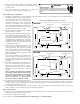
HEAT PUMP REFRIGERANT CIRCUIt - FIGURE 7