
GPH16M Installation Manual


11
Optional Outdoor Thermostat (kit OTHPPKG-01)
This outdoor thermostat is an optional accessory that is pre-set from the factory at 37°F. No other field setting is required. It comes
enclosed in a “birdhouse” and should be mounted on the corner panel near the control panel. Once the ambient temperature falls
below the set temperature of 37°F during heating operation, the thermostat closes and forces the two-stage compressor to run in high
stage.
Reversing Valve Coil
This coil is activated by the thermostat, in the cooling mode and during defrost. It positions the reversing valve pilot valve for cooling
operation.
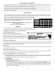
Indoor Blower Motor
All GPH16 M series model package units use a EEM blower
motor. The EEM motor is a 3 Phase brushless DC (single phase
AC input), ball bearing construction motor with an integral control
module with an internal FCC B EMI filter. The EEM motor is
continuously powered with line voltage. The switched 24 volt
control signal is controlled by the thermostat in the cooling and
heat pump mode.
HEAT PUMP OPERATION
COOLING CYCLE
When the heat pump is in the cooling cycle, it operates exactly
as a Air Conditioner unit.
HEATING CYCLE
The heat pump operates in the heating cycle by redirecting
refrigerant flow through the refrigerant circuit external to the
compressor. This is accomplished with through the reversing
valve. Hot discharge vapor from the compressor is directed to
the indoor coil (evaporator on the cooling cycle) where the heat
is removed, and the vapor condenses to liquid. It then goes
through the expansion device to the outdoor coil (condenser on
the cooling cycle) where the liquid is evaporated, and the vapor
goes to the compressor.
When the solenoid valve coil is operated either from heating to
cooling or vice versa, the piston in the reversing valve to the low
pressure (high pressure) reverse positions in the reversing valve.
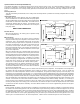
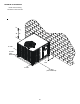
The following figures show a schematic of a heat pump on the
cooling cycle and the heating cycle. In addition to a reversing
valve, a heat pump is equipped with an expansion device and
check valve for the indoor coil, and similar equipment for the
outdoor coil. It is also provided with a defrost control system.
The expansion devices are flowrator distributors and perform
the same function on the heating cycle as on the cooling cycle.
The flowrator distributors also act as check valves to allow for
the reverse of refrigerant flow.
When the heat pump is on the heating cycle, the outdoor coil is functioning as an evaporator. The temperature of the refrigerant in
the outdoor coil must be below the temperature of the outdoor air in order to extract heat from the air. Thus, the greater the
difference in the outdoor temperature and the outdoor coil temperature, the greater the heating capacity of the heat pump. This
phenomenon is a characteristic of a heat pump. It is a good practice to provide supplementary heat for all heat pump installations
in areas where the temperature drops below 45°F. It is also a good practice to provide sufficient supplementary heat to handle the
entire heating requirement should there be a component failure of the heat pump, such as a compressor, or refrigerant leak, etc.
Since the temperature of the refrigerant in the outdoor coil on the heating cycle is generally below freezing point, frost forms on the
surfaces of the outdoor coil under certain weather conditions of temperature and relative humidity. Therefore, it is necessary to
reverse the flow of the refrigerant to provide hot gas in the outdoor coil to melt the frost accumulation. This is accomplished by
reversing the heat pump to the cooling cycle. At the same time, the outdoor fan stops to hasten the temperature rise of the outdoor
coil and lessen the time required for defrosting. The indoor blower continues to run and the supplementary heaters are energized.
DEFROST C ONTROL
During operation the power to the circuit board is controlled by a temperature sensor, which is clamped to a feeder tube entering
the outdoor coil. Defrost timing periods of 30, 60 and 90 minutes may be selected by setting the circuit board jumper to 30, 60 and
90 respectively. Accumulation of time for the timing period selected starts when the sensor closes (approximately 34°F), and when
the wall thermostat calls for heat. At the end of the timing period, the unit’s defrost cycle will be initiated provided the sensor
remains closed. When the sensor opens (approximately 60°F), the defrost cycle is terminated and the timing period is reset. If the
defrost cycle is not terminated due to the sensor temperature, a twelve minute override interrupts the unit’s defrost period.
E
V
A
P
O
R
A
T
O
R
COOLING
SERVICE VALVE
SERVICE PORT
REVERSING VALVE
C
O
N
D
E
N
S
E
R
SERVICE PORT
COMPRESSOR
SERVICE PORT
ACCUMULATOR
EXPANSION DEVICE
CHECK VALVE
ORIFICE
SERVICE
VALVE
CHECK VALVE
ORIFICE
INDOOR
COIL
DISTRIBUTOR
OUTDOOR
COIL
E
V
A
P
O
R
A
T
O
R
HEATING
SERVICE VALVE
SERVICE PORT
REVERSING VALVE
C
O
N
D
E
N
S
E
R
COMPRESSOR
SERVICE PORT
ACCUMULATOR
CHECK VALVE
ORIFICE
SERVICE
VALVE
CHECK VALVE
ORIFICE
INDOOR
COIL
DISTRIBUTOR
OUTDOOR
COIL
DISTRIBUTOR