
GPH16M Installation Manual


12
Suggested Field Testing/Trouble Shooting
1. Run unit in the heating mode (room thermostat calling for heat).
2. Check unit for proper charge. NOTE: Bands of frost on the condenser coil indicate low refrigerant charge.
3. Shut off power to unit.
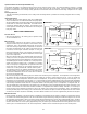
4. Disconnect outdoor fan by removing the outdoor fan motor wire from “DF2” on defrost control.
5. Restart unit and allow frost to accumulate.
6. After a few minutes of operation, the unit’s defrost thermostat should close. To verify this, check for 24 volts between “DFT” and
“C” on board. If the temperature at the thermostat is less than 28°F and the thermostat is open, replace the unit’s defrost
thermostat, as it is defective.
7. When the unit’s defrost thermostat has closed, short the test pins on the defrost board until the reversing valve shifts, indicating
defrost. This should take up to 22 seconds depending on what timing period the control is set on. After defrost initiation, the
short must instantly be removed or the unit’s defrost period will only last 3 seconds.
8. The control is shipped from the factory with the compressor delay option selected. This will de-energize the compressor
contactor for 30 seconds on defrost initiation and defrost termination. If the jumper is set to Normal, the compressor will
continue to run during defrost initiation and defrost termination. The control will also ignore the low pressure switch connected
to R-PS1 and PS2 for 5 minutes upon defrost initiation and 5 minutes after defrost termination.
9. After the unit’s defrost thermostat has terminated, check the defrost thermostat for 24 volts between “DFT” and “C”. The reading
should indicate 0 volts (open sensor).
10. Shut off power to unit.
11. Replace outdoor fan motor lead to terminal “DF2” on defrost board and turn on power.
AIR FLOW M EASUREMENT AND A DJUSTMENT
Please review the Duct Work section before proceeding with the airflow measurements and adjustments in this section.
Unit blower curves (see Specification Sheets) are based on external static pressure (ESP per in/W.C.). The duct openings on the
unit are considered internal static pressure. As long as ESP is maintained, the unit will deliver the proper air up to the maximum
static pressure listed for the CFM required by the application (i.e. home, building, etc.)
In general, 400 CFM per ton of cooling capacity is a rule of thumb. Some applications depending on the sensible and latent
capacity requirements may need only 350 CFM or up to 425 CFM per ton. Check condition space load requirements (from load
calculations) and equipment expanded ratings data to match CFM and capacity.
After unit is set and duct work completed, verify the ESP with a 1-inch inclined manometer with pilot tubes or a Magnahelic gauge
and confirm CFM to blower curves in the Specification Sheets.
NOTE: Never run CFM below 350 CFM per ton, evaporator freezing or poor unit performance is possible.
AIR F LOW ADJUSTMENTS FOR INDOOR BLOWER MOTOR
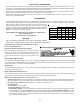
EEM Motor
Adjust the CFM by changing the 24V low voltage lead at the speed terminal block on the motor. (T1-Low Speed, T2 and T3-Medium
Speed, T4 and T5-High Speed).
NOTE: Factory set T1 (G, fan), T2 (cool/Hi cool), T3 (W2 electric heat), T4 and T5 reserved for high static (cool/Hi cool) and W2. Low
cool Y1 will run at G speed.
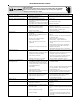
SUPERHEAT CAN BE DETERMINED AS FOLLOWS:
1. Read suction pressure. Determine Saturated Suction Temperature from tables or pressure gauge saturated temperature
scale (R-410A).
2. Read suction line temperature.
3. Use the following formula:
EXPANSION VALVE (TXV) SYSTEM
Two Speed Application (GPH16)
Run the unit on high stage cooling for 10 minutes until refrigerant pressures stabilize. Follow the guidelines and methods below
to check unit operation and ensure that the refrigerant charge is within limits. Charge the unit on high stage.
1. Purge gauge lines. Connect service gauge manifold to access fittings. Run system at least 10 minutes to allow pressure to
stabilize.
2. Temporarily install thermometer on liquid (small) line near liquid line access fitting with adequate contact and insulate for best
possible reading.
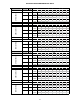
3. Check subcooling and superheat. Two stage systems running on high stage with TXV application should have a subcooling and
superheat within the range listed on the chart.
a. If subcooling and superheat are low, adjust TXV superheat, then check subcooling.
NOTE: To adjust superheat, turn the valve stem clockwise to increase and counter clockwise to decrease.
b. If subcooling is low and superheat is high, add charge to raise subcooling then check superheat.