
GPH16H Installation Instructions


5
The unit should be set on a solid, level foundation - preferably a concrete
slab at least 4 inches thick. The slab should be above ground level and
surrounded by a graveled area for good drainage. Any slab used as a
unit’s foundation should not adjoin the building as it is possible that
sound and vibration may be transmitted to the structure. For rooftop
installation, steel or treated wood beams should be used as unit support
for load distribution.
Heat pumps require special location consideration in areas of heavy
snow accumulation and/or areas with prolonged continuous subfreezing
temperatures. Heat pump unit bases have holes under the outdoor coil
to permit drainage of defrost water accumulation. The unit must be
situated to permit free unobstructed drainage of the defrost water and
ice. A minimum 2" clearance under the outdoor coil is required in the
milder climates.
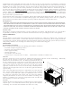
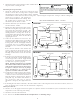
Outside Slab Installation (Figure 1)
1. The unit must be mounted on a solid, level foundation.
2. Select a location that will minimize the length of the supply and
return ducts.
3 Select a location where external water drainage cannot collect around
the unit.
4. Consideration should also be given to shade, appearance
and noise.
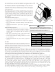
Rooftop Installation (Figure 2)
1. Before locating the unit on the roof, make sure that the
strength of the roof and beams is adequate to support
the weight involved. (See specification sheet for weight
of units.) This is very important and the installer’s
responsibility.
2. Make proper consideration for the weather–tight integrity
of the roof and proper drainage of condensate.
3. To ensure proper condensate drainage, unit must be installed
in a level position.
4. Consideration should also be given to shade, appearance
and noise.
DUCTING
Ducting work should be fabricated by the installing contractor in
accordance with local codes. Industry manuals may be used as a
guide when sizing and designing the duct system- such as NESCA
(National Environmental Systems Contractors Association, 1501
Wilson Blvd., Arlington, Virginia 22209).
The unit should be placed as close as possible to the space to be air-conditioned allowing clearance dimensions as
indicated. Ducts should run as directly as possible to supply and return outlets. Use of non-flammable weatherproof
flexible connectors on both supply and return connections at the unit to reduce noise transmission is recommended.
It is preferable to install the unit on the roof of the structure if the registers or diffusers are located in the wall or
ceiling. A slab installation is recommended when the registers are low on the wall or in the floor.
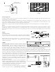
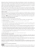
Connecting the Return and Supply Flexible Duct in Manufactured or Modular Housing Application
The return and supply fittings are to be attached at the unit to a suitable square to round duct converter. Your
distributor has a factory designed square to round converter transition. The model #’s of these kits are as follows:
Small Chassis 25” SQRPCH101, Medium Chassis 27.5” SQRPCH102, Large and Extra Large Chassis 32.5:” and 36” SQRPCH103
(See Specification Sheets for Dimension details). The SQRPCH101 has 14" duct collar on supply and 16" duct collar
(equivalent diameter, opening is oval) on the return. The SQRPCH102 and SQRPCH103 have 14" duct collar on supply
and 18" duct collar (equivalent diameter, opening is oval) on the return. The collars are to be slipped into the
openings, and the flanges bent around the converter. The square to round converter is attached to the flanges of the
square duct openings. The flexible duct is then clamped on to the collars. Once the duct is affixed to the unit, seal
the collars and flanges with a proper waterproof sealant (See Figure 3).
It is strongly encouraged to use appropriately sized ducts based upon the CFM for your application (unit’s CFM). If
duct sizing through industry manuals or air duct calculators require larger ducts than converter openings, run larger
duct size up to unit converter openings and reduce with a reducer duct fitting or transition right at the unit.
36"
36"
24"
P
L
E
N
U
M
U
N
I
T
P
L
A
T
F
O
R
M
C
U
R
B
FIGURE 2
WARNING
D
O
NOT
,
UNDER
ANY
CIRCUMSTANCES
,
CONNECT
RETURN
DUCT
-
WORK
TO
ANY
OTHER
HEAT
PRODUCING
DEVICES
SUCH
AS
FIRE
-
PLACE
INSERT
,
STOVE
,
ETC
. U
NAUTHORIZED
USE
OF
SUCH
DEVICES
MAY
RESULT
IN
PROPERTY
DAMAGE
,
FIRE
,
CARBON
MONOXIDE
POISONING
,
EXPLOSION
,
PERSONAL
INJURY
OR
DEATH
.
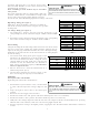
NOMINAL SIZE (INCHES) NOMINAL AREA (SQ. FT.)
10x20 1.4
14x20 1.9
14x25 2.4
15x20 2.1
16x20 2.2
16x25 2.8
20x20 2.8
20x25 3.5
25x25 4.3
MINIMUM FILTER SIZE
TABLE 1