
GPH16M Installation Manual


8
cleaning. When installing filters, ensure the air flow arrows on the filter
are pointing toward the circulator blower.
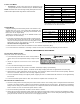
Refer to the unit filter size chart below for filter size information.
NOMINAL SIZE (INCHES) NOMINAL AREA (SQ. FT.)
10x20 1.4
14x20 1.9
14x25 2.4
15x20 2.1
16x20 2.2
16x25 2.8
20x20 2.8
20x25 3.5
25x25 4.3
MINIMUM FILTER SIZE
500 1000 1500 2000 2500 3000 3500
7
6
5
4
3
2
D
I
S
P
O
S
A
B
L
E
F
I
L
T
E
R
P
E
R
M
A
N
E
N
T
F
I
L
T
E
R
Airflow - SCFM
N
o
m
i
n
a
l
F
i
l
t
e
r
A
r
e
a
S
q
u
a
r
e
F
e
e
t
NOTE: Filters must have adequate face area for the rated quantity of the
unit. See the air delivery table below for recommended filter size. Size
the filters in accordance with their manufacturer recommendations.
Throwaway filters must be sized for a maximum face velocity of 300 feet
per minute.
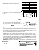
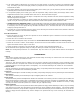
PIPING
C
ONDENSATE D RAIN
The condensate drain connection of the evaporator is a half coupling of ¾”
N.P.T. A trap must be provided to have proper condensate drainage.
Install condensate drain trap as shown. Use ¾ “ drain connection size or
larger. Do not operate without trap. Unit must be level or slightly inclined
toward drain.
WIRING
NOTE: All wiring should be made in accordance with the National Electrical
Code.
Consult your local Power Company to determine the availability of sufficient power to operate the unit. Check the voltage, frequency,
and phase at the power supply to ensure it corresponds to the unit’s RATED VOLTAGE REQUIREMENT.
In accordance with the N.E.C. or local codes, install a branch circuit fused disconnect near the unit. Determine wire sizes and
overcurrent protection from the unit nameplate ampacity and in accordance with the Minimum Filter Size or the N.E.C. The wiring
should never be sized smaller than is recommended by either of these two sources.
Fuses smaller than that recommended on the rating plate could result in unnecessary fuse failure or service calls. The use of
protective devices of larger size than indicated could result in extensive damage to the equipment. The manufacturer bears no
responsibility for damage caused to equipment as result of the use of larger than is recommended size protective devices.
All units have undergone a run test prior to packaging for shipment. This equipment has been started at minimum rated voltage
and checked for satisfactory operation. Do not attempt to operate this unit if the voltage is not within the minimum and maximum
voltages shown on nameplate.
All exterior wiring must be within approved weatherproof conduit. The unit must be permanently grounded in accordance with
local codes, or in absence of local codes, with N.E.C. ANSI/ NFPA NO. 70-1984 or latest edition by using ground lug in the control
box.
Fuses or HACR type circuit breakers may be used where codes permit.
IMPORTANT NOTE: Some single phase units are equipped with a single-pole contactor. Exercise caution when servicing as only
one leg of the power supply is broken with the contractor.
HIGH V OLTAGE W IRING
• Single Phase. Connect two leads to terminals L1 & L2 in
the electrical control section, using wire sizes specified in
wiring table.
2" Minimum
3" Minimum
A Positive Liquid Seal
Is Required
Flexible
Tubing-Hose
Or Pipe
Drain
Connection
Unit