
Service Manual

SERVICING
29
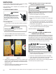
S-16C CHECKING ECM MOTOR WINDINGS
HIGH VOLTAGE!
Disconnect ALL power before servicing
or installing this unit. Multiple power
sources may be present. Failure to do so
may cause property damage, personal injury
or death.
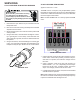
1. Disconnect the 5-pin and the 16-pin connectors from the
ECM power head.
2. Remove the 2 screws securing the ECM power head and
separate it from the motor.
3. Disconnect the 3-pin motor connector from the power head
and lay it aside.
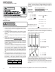
4. Using an ohmmeter, check the motor windings for continu-
ity to ground (pins to motor shell). If the ohmmeter indi-
cates continuity to ground, the motor is defective and must
be replaced.
5. Using an ohmmeter, check the windings for continuity (pin
to pin). If no continuity is indicated, the thermal limit (over
load) device may be open. Allow motor to cool and retest.
Motor
Connector
(3-pin)
Motor OK when
R > 100k ohm
(3-pin)
WINDING TEST
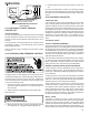
S-16D CHECKING EEM MOTORS
Applies to A/GPG15*****41A*
The EEM motor is a one piece, fully encapsulated, 3 phase
brushless DC (single phase AC input) motor with ball bearing
construction. Unlike the ECM 2.3/2.5 motors, the EEM fea-
tures an integral control module.
Note: The GE TECMate will not currently operate the EEM
motor.
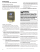
EEM MOTOR CONNECTIONS
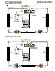
1. Using a voltmeter, check for 230 volts to the motor connec-
tions L and N. If 230 volts is present, proceed to step 2. If
230 volts is not present, check the line voltage circuit to
the motor.
2. Using a voltmeter, check for 24 volts from terminal C to
either terminal 1, 2, 3, 4, or 5, depending on which tap is
being used, at the motor. If voltage present, proceed to
step 3. If no voltage, check 24 volt circuit to motor.
3. If voltage was present in steps 1 and 2, the motor has failed
and will need to be replaced.
Note: When replacing motor, ensure the belly band is between
the vents on the motor and the wiring has the proper drip loop
to prevent condensate from entering the motor.