
Service Manual


SERVICING
35
5. Continue to evacuate to a minimum of 250 microns. Close
valve to vacuum pump and watch rate of rise. If vacuum
does not rise above 1500 microns in three to five minutes,
system can be considered properly evacuated.
6. If thermocouple vacuum gauge continues to rise and levels
off at about 5000 microns, moisture and non-condensables
are still present. If gauge continues to rise a leak is present.
Repair and re-evacuate.
7. Close valve to thermocouple vacuum gauge and vacuum
pump. Shut off pump and prepare to charge.
S-103 CHARGING
WARNING
ONLY USE REFRIGERANT CERTIFIED TO AHRI STANDARDS. USED
REFRIGERANT MAY CAUSE COMPRESSOR DAMAGE. GOODMAN
IS NOT RESPONSIBLE FOR DAMAGE OR THE NEED FOR REPAIRS
RESULTING FROM THE USE OF UNAPPROVED REFRIGERANT TYPES
OR USED OR RECYCLED REFRIGERANT. MOST PORTABLE MACHINES
CANNOT CLEAN USED REFRIGERANT TO MEET AHRI STANDARDS.
CAUTION
Charge the system with the exact amount of refrigerant.
Refer to the specification section or check the unit nameplates
for the correct refrigerant charge.
An inaccurately charged system will cause future prob-
lems.
1. Using a calibrated set of refrigerant scales, allow liquid re-
frigerant only to enter the high side.
2. After the system will take all it will take, close the valve on
the high side of the charging manifold.
3. Start the system and charge the balance of the refrigerant
through the low side.
NOTE: R410A should be drawn out of the storage container or
drum in liquid form due to its fractionation properties, but should
be "Flashed" to its gas state before entering the system. There
are commercially available restriction devices that fit into the
system charging hose set to accomplish this. DO NOT charge
liquid R410A into the compressor.
4. With the system still running, close the valve on the charg-
ing cylinder. At this time, you may still have some liquid
refrigerant in the charging cylinder hose and will definitely
have liquid in the liquid hose. Reseat the liquid line core.
Slowly open the high side manifold valve and transfer the
liquid refrigerant from the liquid line hose and charging cyl-
inder hose into the suction service valve port. CAREFUL:
Watch so that liquid refrigerant does not enter the com-
pressor.
Final Charge Adjustment
The outdoor temperature must be 60°F or higher. Set the room
thermostat to COOL, fan switch to AUTO, and set the tem-
perature control well below room temperature.
After system has stabilized per startup instructions, compare
the operating pressures and outdoor unit amp draw to the num-
bers listed in the technical manual. If pressures and amp draw
are too low, add charge. If pressures and amp draw are too
high, remove charge. Check subcooling and superheat as de-
tailed in the following section.
5. With the system still running, remove hose and reinstall
both valve caps.
6. Check system for leaks.
Due to their design, Scroll compressors are inherently more
tolerant of liquid refrigerant.
NOTE: Even though the compressor section of a Scroll com-
pressor is more tolerant of liquid refrigerant, continued flood-
back or flooded start conditions may wash oil from the bearing
surfaces causing premature bearing failure.
S-104 CHECKING COMPRESSOR EFFICIENCY
The reason for compressor inefficiency is broken or dam-
aged suction and/or discharge valves, or scroll flanks on Scroll
compressors, reducing the ability of the compressor to pump
refrigerant vapor.
The condition of the valves or scroll flanks is checked in the
following manner.
1. Attach gauges to the high and low side of the system.
2. Start the system and run a Cooling Performance Test.
If the test shows-
⇒
Below normal high side pressure.
⇒
Above normal low side pressure.
⇒
Low temperature difference across coil.
⇒
Low amp draw at compressor.
-and the charge is correct. The compressor is faulty - replace
the compressor.
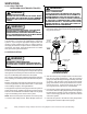
S-105 THERMOSTATIC EXPANSION VALVE
The expansion valve is designed to control the rate of liquid
refrigerant flow into an evaporator coil in exact proportion to the
rate of evaporation of the refrigerant in the coil. The amount of
refrigerant entering the coil is regulated since the valve responds
to temperature of the refrigerant gas leaving the coil (feeler bulb
contact) and the pressure of the refrigerant in the coil. This
regulation of the flow prevents the return of liquid refrigerant to
the compressor.
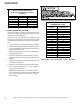
The illustration below shows typical heatpump TXV/check valve
operation in the heating and cooling modes.