
Service Manual


SERVICING
36
Wiring is subject to change. Always refer to the wiring diagram on the unit for the most up-to-date wiring.
COOLING HEATING
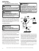
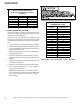
TXV VALVES
Some TXV valves contain an internal check valve thus eliminat-
ing the need for an external check valve and bypass loop. The
three forces which govern the operation of the valve are: (1) the
pressure created in the power assembly by the feeler bulb, (2)
evaporator pressure, and (3) the equivalent pressure of the su-
perheat spring in the valve.
0% bleed type expansion valves are used on indoor and out-
door coils. The 0% bleed valve will not allow the system pres-
sures (High and Low side) to equalize during the shut down
period. The valve will shut off completely at approximately 100
PSIG.
30% bleed valves used on some other models will continue to
allow some equalization even though the valve has shut-off
completely because of the bleed holes within the valve. This
type of valve should not be used as a replacement for a 0%
bleed valve, due to the resulting drop in performance.
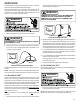
The bulb must be securely fastened with two straps to a clean
straight section of the suction line. Application of the bulb to a
horizontal run of line is preferred. If a vertical installation can-
not be avoided, the bulb must be mounted so that the capillary
tubing comes out at the top.
THE VALVES PROVIDED BY GOODMAN ARE DESIGNED
TO MEET THE SPECIFICATION REQUIREMENTS FOR OP-
TIMUM PRODUCT OPERATION. DO NOT USE SUBSTI-
TUTES.
S-106 OVERFEEDING
Overfeeding by the expansion valve results in high suction pres-
sure, cold suction line, and possible liquid slugging of the com-
pressor.
If these symptoms are observed:
1. Check for an overcharged unit by referring to the cooling
performance charts in the servicing section.
2. Check the operation of the power element in the valve as
explained in S-110 Checking Expansion Valve Operation.
3. Check for restricted or plugged equalizer tube.
S-107 UNDERFEEDING
Underfeeding by the expansion valve results in low system
capacity and low suction pressures.
If these symptoms are observed:
1. Check for a restricted liquid line or drier. A restriction will
be indicated by a temperature drop across the drier.
2. Check the operation of the power element of the valve as
described in S-110 Checking Expansion Valve Operation.
S-108 SUPERHEAT
The expansion valves are factory adjusted to maintain 15 to 18
degrees superheat of the suction gas. Before checking the
superheat or replacing the valve, perform all the procedures
outlined under Air Flow, Refrigerant Charge, Expansion Valve -
Overfeeding, Underfeeding. These are the most common
causes for evaporator malfunction.
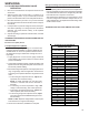
CHECKING SUPERHEAT
Refrigerant gas is considered superheated when its tempera-
ture is higher than the saturation temperature corresponding to
its pressure. The degree of superheat equals the degrees of
temperature increase above the saturation temperature at ex-
isting pressure. See Temperature - Pressure Chart on follow-
ing pages.
S-109 CHECKING SUBCOOLING
Refrigerant liquid is considered subcooled when its tempera-
ture is lower than the saturation temperature corresponding to
its pressure. The degree of subcooling equals the degrees of
temperature decrease below the saturation temperature at the
existing pressure.
1. Attach an accurate thermometer or preferably a thermo-
couple type temperature tester to the liquid line close to
the high pressure access fitting process tube.
2. Install a high side pressure gauge on the high side (liquid)
access fitting.
3. Record the gauge pressure and the temperature of the line.
4. Review the technical information manual or specification
sheet for the model being serviced to obtain the design
subcooling.
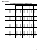
5. Compare the hi-pressure reading to the "Required Liquid
Line Temperature" chart . Find the hi-pressure value on the
left column. Follow that line right to the column under the
design subcooling value. Where the two intersect is the
required liquid line temperature.
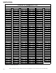
Alternately you can convert the liquid line pressure gauge
reading to temperature by finding the gauge reading in Tem-
perature - Pressure Chart and reading to the left, find the
temperature in the °F. Column.
6. The difference between the thermometer reading and pres-
sure to temperature conversion is the amount of subcooling.
Add charge to raise subcooling. Recover charge to lower
subcooling.
SUBCOOLING = SAT. LIQUID TEMP. - LIQUID LINE TEMP.
EXAMPLE:
a. Liquid Line Pressure = 417
b. Corresponding Temp. °F. = 120°
c. Thermometer on Liquid line = 113°F.
To obtain the amount of subcooling subtract 113°F from 120°F.
The difference is 7° subcooling, which would fall in the
+ range
of allowable subcooling.