
Service Manual


SERVICING
37
S-110 CHECKING EXPANSION VALVE
OPERATION
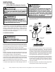
1. Remove the remote bulb of the expansion valve from the
suction line.
2. Start the system and cool the bulb in a container of ice
water, closing the valve. As you cool the bulb, the suction
pressure should fall and the suction temperature will rise.
3. Next warm the bulb in your hand. As you warm the bulb,
the suction pressure should rise and the suction tempera-
ture will fall.
4. If a temperature or pressure change is noticed, the expan-
sion valve is operating. If no change is noticed, the valve is
restricted, the power element is faulty, or the equalizer
tube is plugged.
5. Capture the charge, replace the valve and drier, evacuate
and recharge.
SUPERHEAT AND SUBCOOLING ADJUSTMENT ON TXV
APPLICATIONS
EXPANSION VALVE (TXV) SYSTEM
Two Speed Application (APH16)
Run the unit on high stage cooling for 10 minutes until
refrigerant pressures stabilize. Follow the guidelines and
methods below to check unit operation and ensure that
the refrigerant charge is within limits. Charge the unit on
high stage.
1. Purge gauge lines. Connect service gauge manifold to
access fittings. Run system at least 10 minutes to allow
pressure to stabilize.
2. Temporarily install thermometer on liquid (small) line near
liquid line access fitting with adequate contact and insu-
late for best possible reading.
3. Check subcooling and superheat. Two stage systems run-
ning on high stage with TXV application should have a
subcooling and superheat within the range listed on the
chart.
a. If subcooling and superheat are low, adjust TXV
superheat, then check subcooling.
NOTE: To adjust superheat, turn the valve stem
clockwise to increase and counter clockwise to
decrease.
b. If subcooling is low and superheat is high, add
charge to raise subcooling then check superheat.
c. If subcooling and superheat are high, adjust TXV
valve superheat, then check subcooling.
d. If subcooling is high and superheat is low, adjust
TXV valve superheat and remove charge to lower
the subcooling.
NOTE: Do NOT adjust the charge based on suction pres-
sure unless there is a gross undercharge.
4. Disconnect manifold set, installation is complete.
Refrigerant Charge Check (Units with Fixed Orifice
Devices)
After completing airflow measurements and adjustments
the unit’s refrigerant charge must be checked. All package
units with fixed orifice devices are charged using the super
heat method at the compressor suction line.
After superheat is adjusted it is recommended to check
unit sub-cooling at the condenser coil liquid line out. For
charge adjustments, see superheat and subcooling charts
shown for each model.
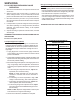
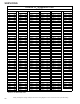
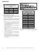
SUPERHEAT=SUCTION LINE TEMP-SUCTION TEMP
SUCTION PRESSURE
SATURATED SUCTION
TEMPERATURE ºF
PSIG R-410A
50 1
52 3
54 4
56 6
58 7
60 8
62 10
64 11
66 13
68 14
70 15
72 16
74 17
76 19
78 20
80 21
85 24
90 26
95 29
100 31
110 36
120 41
130 45
140 49
150 53
160 56
170 60
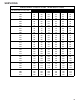
SATURATED SUCTION PRESSURE
TEMPERATURE CHART