
Service Manual


18
SYSTEM OPERATION
EM ERGENCY HEAT M ODE (HEAT PUM PS)
NOTE: The following only applies if the unit has an approved
elect ric heat kit installed for auxiliary heat ing.
* PH M ODELS EQUIPPED W ITH EEM BLOW ER M OTORS
With the thermost at set to the emergency heat position, R to
W1 will be energized. This will energize the electric heat se-
quencers and the EEM
motor. The electric heat will be ener-
gized t hrough t he normally open contacts of the electric heat
sequencers. The indoor blower will be energized through W
from the thermost at .
DEFROST CYCLE
PACKAGE HEAT PUM PS
The defrosting of the out door coil is jointly controlled by the
defrost cont rol board and the defrost thermost at.
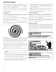
SOLID STATE DEFROST CONTROL
During operation the pow er to the circuit board is controlled
by a temperature sensor, which is clamped to a feeder tube
ent ering t he outdoor coil. Defrost timing periods of 30, 60, or
90 minutes may be selected by sett ing t he circuit board jumper
to 30, 60, or 90 respect ively. Accumulat ion of time for t he tim-
ing period selected st arts when the sensor closes (approximat ely
32
+ 2° F), and when the room thermost at calls for heat. At the
end of the timing period, the unit’s defrost cycle will be initi-
ated provided the sensor remains closed. When the sensor
opens (approximately 60° F), the defrost cycle is t erminated
and the timing period is reset. If the defrost cycle is not termi-
nated due to the sensor temperature, a twelve minute over-
ride interrupts t he unit’s defrost period.
FAN OPERATION
CONTINUOUS FAN M ODE
M ODELS EQUIPPED W ITH EEM BLOW ER M OTORS
If the t hermostat calls for cont inuous fan, the indoor blower
will be energized from the G terminal of the thermostat t o the
EEM blower motor.
If a call for heat or cool occurs during a continuous fan call, the
EEM motor will alw ays recognize t he call for the highest speed
and ignore the lower speed call.
If the t hermostat is not calling for heat or cool, and the fan
swit ch on t he t hermostat is ret urned to the automat ic posi-
tion, t he fan will st op aft er the programmed 60 second off de-
lay on unit s wit h the EEM mot or.
A/ GPC15 & A/ GPH16H41* *
ECM M OTOR
SPEED ADJUSTM ENT
Each ECM blow er mot or has been preprogrammed for opera-
tion at 4 dist inct air flow levels when operating in Cooling/ Heat
Pump mode or Electric Heat mode. These 4 distinct levels may
also be adjusted slight ly lower or higher if desired. The adjust -
ment bet w een levels and the t rim adjust ments are made by
changing the dip switch(s) eit her to an "OFF" or "ON" posit ion.
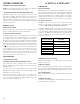
DIP SW ITCH FUNCTIONS
The ECM motor has an electronic control that contains eight
(8) 2-posit ion dip switches. The function of these dip swit ches
is shown in Table 6, Airflow charts pages 42 and 43.
For APC15 / APH16 [24-36] models, dip sw itch 4 must be set
to ON. Dip sw itch 4 must be set to OFF for two-st age compres-
sor models APC15 / APH16 [48-60]. Dip switch 4 ON energizes
Y1 signal t o the ECM mot or anytime Y/ Y2 is energized. The in-
door mot or will not operat e properly if switch is not set cor-
rectly for the model.
DIP SW ITCH NUMBER FUNCTION
1
2
3N/A
4Indoor Thermostat
5
6
7
8
Cooling & Heat Pump CFM
CFM Tri m Ad ju s t
El e ctri c Hea t
TABLE 6
THERM OSTAT “FAN ONLY” M ODE
During Fan Only Operations, the CFM output is 50% of the high
stage cooling setting.
HUM IDITY CONTROL
When using a Humidist at (normally closed), cut jumper PJ6 on
the cont rol board. The Humidist at will only affect both low st age
and high st age cooling air flow by adjusting t he Air flow to 85%.
TWO-STAGE HEATING
When using st aged elect ric heat, cut jumper PJ4 on the control
board.
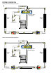
THERM OSTAT W IRING
Use thermost at wiring diagrams provided wit h the t hermost at
when making these connections.