
Service Manual


SERVICING
32
S-101 LEAK TESTING
(NITROGEN OR NITROGEN-TRACED)
WARNING
WARNING
Pressure test t he syst em using dry nitrogen and soapy w ater to
locate leaks. If you wish to use a leak det ector, charge the sys-
tem to 10 psi using the appropriate refrigerant then use nitro-
gen to finish charging t he syst em to working pressure, then ap-
ply the detector to suspect areas. If leaks are found, repair them.
Aft er repair, repeat the pressure t est . If no leaks exist, proceed
to syst em evacuation.
For a syst em that contains a refrigerant charge and is suspected
of having a leak, st op the operation and hold the exploring t ube
of the det ector as close to the t ube as possible, check all piping
and fitt ings. If a leak is det ect ed, do not att empt to apply more
brazing to the joint . Remove and capt ure the charge, unbraze
the joint , clean and rebraze.
For a syst em that has been new ly repaired and does not contain
a charge, connect a cylinder of refrigerant, through a gauge mani-
fold, to the liquid and suct ion line dill valves and/ or liquid line
dill valve and compressor process tube.
NOTE: Refrigerant hoses must be equipped with dill valve de-
pressors or special adaptor used. Open the valve on the cylinder
and manifold and allow the pressure to build up wit hin the sys-
tem. Check for and handle leaks, as described above. After the
test has been complet ed, remove and capture t he leak test re-
frigerant .
S-102 EVACUATION
WARNING
This is the most import ant part of the entire service procedure.
The life and efficiency of t he equipment is dependent upon t he
thoroughness exercised by the serviceman when evacuating air
(non-condensable) and moisture from the syst em.
Air in a system causes high condensing temperature and pres-
sure, resulting in increased pow er input and reduced performance.
M oisture chemically react s with the refrigerant and oil to form
corrosive hydrofluoric and hydrochloric acids. These attack mo-
tor windings and parts, causing breakdown.
The equipment required to thoroughly evacuat e t he syst em is a
high vacuum pump, capable of producing a vacuum equivalent
to 25 microns absolut e and a t hermocouple vacuum gauge t o
give a true reading of the vacuum in t he syst em
NOTE: Never use t he syst em compressor as a vacuum pump or
run when under a high vacuum. M otor damage could occur.
WARNING
SCROLL COMPRESSORS
DO NOT FRONT SEAT THE SERVICE VALVE(S) WITH
THE COMPRESSOR OPERATING IN AN ATTEMPT TO
SAVE REFRIGERANT. WITH THE SUCTION LINE OF
THE COMPRESSOR CLOSED OR SEVERLY RESTRICT-
ED, THE SCROLL COMPRESSOR WILL DRAW A DEEP
VACUUM VERY QUICKLY. THIS VACUUM CAN CAUSE
INTERNAL ARCING OF THE FUSITE RESULTING IN A
DAMAGED OR FAILED COMPRESSOR.
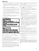
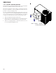
LOW SIDE
GAUGE
AND VALVE
HIGH SIDE
GAUGE
AND VALVE
1. Connect the vacuum pump, vacuum tight manifold set with
high vacuum hoses, thermocouple vacuum gauge and charg-
ing cylinder as shown.
2. St art the vacuum pump and open the shut off valve t o the
high vacuum gauge manifold only. Aft er the compound gauge
(low side) has dropped t o approximat ely 29 inches of
vacuum, open the valve to the vacuum thermocouple gauge.
See that the vacuum pump will blank-off to a maximum of 25
microns. A high vacuum pump can only produce a good
vacuum if its oil is non-contaminated.