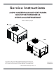
Service Instructions A/GPH 16 SEER PACKAGE HEAT PUMPS MULTI-POSITION MODELS WITH R-410A REFRIGERANT Model numbers on page 6. 2-4 TON 5 TON This manual is to be used by qualified, professionally trained HVAC technicians only. Goodman does not assume any responsibility for property damage or personal injury due to improper service procedures or services performed by an unqualified person. RS6334001r3 October 2016 © 2016 Goodman Manufacturing Company, L.P.
INDEX IMPORTANT INFORMATION ....................................................................................................... 4-5 PRODUCT IDENTIFICATION .......................................................................................................... 6 ACCESSORIES ............................................................................................................................... 7 GPGHFR101-103 ........................................................................................
INDEX S-16A Checking Fan and Blower Motor Windings (PSC Motors) ......................................................... 29 S-16C Checking ECM Motor Windings ................................................................................................... 29 S-16D Checking EEM Motors .................................................................................................................... 29 S-17C UNLOADER TEST PROCEDURE...........................................................................
IMPORTANT INFORMATION Pride and workmanship go into every product to provide our customers with quality products. It is possible, however, that during its lifetime a product may require service. Products should be serviced only by a qualified service technician who is familiar with the safety procedures required in the repair and who is equipped with the proper tools, parts, testing instruments and the appropriate service manual.
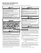
IMPORTANT INFORMATION SAFE REFRIGERANT HANDLING While these items will not cover every conceivable situation, they should serve as a useful guide. WARNING WARNING TO AVOID POSSIBLE EXPLOSION: • NEVER APPLY FLAME OR STEAM TO A REFRIGERANT CYLINDER. IF YOU REFRIGERANTS ARE HEAVIER THAN AIR. THEY CAN "PUSH OUT" THE T O AVOID OXYGEN IN YOUR LUNGS OR IN ANY ENCLOSED SPACE.
PRODUCT IDENTIFICATION The model number is used for positive identification of component parts used in manufacturing. Please use this number when requesting service or parts information. S in g l e P h a se M u ltip o sitio n H e a t P u m p M ode l # D e sc ri p ti o n ® A P H 16 [ 2 4-4 8 ]M 4 1 A A A m a n a B ra nd P a c k a g e H e a t P u m p u p to 1 6 S E E R R 4 10 A M u lt ip o s it io n h e a tin g / c o o lin g u n its . Initial re le a s e o f s in gle p h a s e m o d e ls .
ACCESSORIES A/GPH16[24-48]M41* ACCESSORIES - A/GPH16**M MODELS Part Number Description OT18-60A Outdoor Thermostat Kit w/Lockout Stat OT/EHR18-60 Emergency Heat Relay Kit HKP[05,10,15,20]; HKR08 Single Phase 208-230 Volt Electric Heat Kit HKR3 Three Phase 208-230 Volt Electric Heat Kit PGC101/102/103 Roof Curb DHZECNJPGCHM Goodman/Daikin Horizontal Jade Economizer M Series Package Unit All Fuels, Medium Chassis, H Series All Fuels, All Chassis DHZECNJPGCHL Goodman/Daikin Horizontal Jade Eco
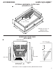
A/GPH/16[24-48]M41* ACCESSORIES EXTERNAL HORIZONTAL FILTER RACK (GPGHFR101-103) 16" 24" 4" 16" x 25" x 2" FILTER 26 1/2" 17 1/4" Filter Size: 16" x 25" x 2" (Requires 1 filter) Measurement in inches DOWNFLOW FILTER RACK (GPH13MFR) PANEL SIDE VIEW DUCT SIDE VIEW FILTER PLATFORM LEFT SIDE RIGHT SIDE DOWNFLOW R/A DUCT OPENING EVAPORATOR COIL Filter Size: 14" x 25" x 2" (Requires 2 filters) - Measurement in inches 8
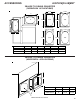
ACCESSORIES A/GPH16[24-48]M41* MOTORIZED/MANUAL FRESH AIR DAMPERS (HORIZONTAL APPLICATIONS) B 7 5/8 5 3/4 11 7/8 A B A Manual Fresh Air Dampers MODEL A B PGMDH102 31 1/2 29 3/4 PGMDH103 39 29 3/4 Motorized Fresh Air Dampers MODEL A B PGMDMH102 31 1/2 29 3/4 PGMDMH103 39 29 3/4 MOTORIZED/MANUAL FRESH AIR DAMPERS (DOWNFLOW APPLICATIONS) BOTTOM VIEW 12 1/8 6 5 3/4 10 11 7/8 1 PGMDD103 BOTTOM VIEW 12 1/8 10 5 3/4 6 11 7/8 1 PGMDD101/102 Manual Fresh Air Dampers MODEL A B PGMDD101/
ACCESSORIES A/GPH16[24-48]M41* SQUARE TO ROUND CONVERTER (DOWNFLOW APPLICATIONS) 12 1/4 14 3/4 C D S 16 ø 22 3/4 16 ø 22 1/4 R A 12 1/4 14 3/4 B 22 3/4 22 1/4 18 ø 18 ø MODEL A B C D RETURN SUPPLY SQRPG101/102 22 3/4 12 1/4 22 1/4 14 3/4 16 16 SQRPG103 22 3/4 12 1/4 22 1/4 14 3/4 18 18 SQUARE TO ROUND CONVERTER (HORIZONTAL APPLICATIONS) B C MODEL A B C SQRPGH101/102 16 16 1/2 16 1/2 S QRP GH103 18 18 1/2 18 1/2 A Measurements are in inches.
ACCESSORIES A/GPH16[24-48]M41* ECONOMIZER GPJMED102 (DOWNFLOW APPLICATIONS) E C D F B PGED101/102 A B C D E F 20 16.25 16 23.5 12.5 45.
A/GPH16[24-48]M41* ACCESSORIES ECONOMIZER DHZECNJPGCH[M/L] (HORIZONTAL APPLICATIONS) B 16 1/8 18 D A E C MODEL A B C DHZECNJPGCHM 25 1/4 18 18 DHZECNJPGCHL 35 1/4 18 1/8 D E FILTER 18 13 3/4 16 1/8 16 X 25 X1 18 18 1/4 16 1/8 16 X 25 X1 Measurements in inches ROOF CURBS B S A R C 1 5/8 14 1/2 1 3/8 MODEL A B C RETURN SUPPLY PGC101/102/103 46 1/4* 39 3/8* 14 1/2 12 1/2 x 23* 15 x 22 1/2* *Inside Dimensions 12
ACCESSORIES HEAT PUMP A/GPH1660M41 Part Number 14CURB3672 D25FD3672 D25MFD3672 CDK4872 DDNECNJ3672B DDNECNJ3672NR DDNSQRD487218 DHZECNJ3672 DBRD3672 LAKT01 Description 14'' Roof Curb 25% Manual Fresh Air Damper 25% Motorized Fresh Air Damper Concentric Duct Kit Low-Leak Downflow Economizer Downflow Economizer w/o Barometric Relief Downflow Square to Round Adapter (18'' Round) Electric Heat Kits Horizontal Economizer Barometric Relief Damper Low Ambient Kit 13
ACCESSORIES ROOF CURBS 14CURB3672 A B C D14CURB3672 Cha ssis #1 Mode l 5 Ton A 70 3/4" B 37" C 14" Measurement in inches DOWNFLOW SQUARE TO ROUND ADAPTERS DDNSQRD4872148 A C B D Measurement in inches DOWNFLOW SQUARE TO ROUND ADAPTER MODEL DDNSQRD487218 SIZE 18" ROUND A 13.50 B 31.125 C 19.50 D 19.
ACCESSORIES MOTORIZED/MANUAL FRESH AIR DAMPERS 25% FRESH AIR DAMP ER CHAS SIS #1 MODEL 5 TON MANUAL D25FD3672 MOTORIZED D25MFD3672 ECONOMIZERS HORIZONTAL ECONOMIZER MODEL DHZECNJ3672 TYPE HORIZONTAL MODEL 5 TON DOWNFLOW ECONOMIZER MODEL DDNECNJ3672B TYPE DOWNFLOW (MCDANIEL METALS) MODEL 5 TON DDNECNJ3672NR DOWNFLOW W/O BAROMETRIC RELIEF (MCDANIEL METALS) 5 TON 15
PRODUCT DESIGN LOCATION & CLEARANCES NOTE: To ensure proper condensate drainage, unit must be installed in a level position. In installations where the unit is installed above ground level and not serviceable from the ground (Example: Roof Top installations) the installer must provide a service platform for the service person with rails or guards in accordance with local codes or ordinances. moval, to allow service access and to insure proper ventilation and condenser airflow.
PRODUCT DESIGN The connecting ductwork (Supply and Return) can be connected for horizontal discharge airflow. In the down discharge applications, a matching Roof Curb is recommended. A return air filter must be installed behind the return air grille(s) or provision must be made for a filter in an accessible location within the return air duct. The minimum filter area should not be less than those sizes listed in the Specification Section.
PRODUCT DESIGN ELECTRICAL WIRING The units are designed for operation at the voltages and frequency as shown on the rating plate. All internal wiring is complete. Ensure the power supply to the compressor contactor is brought to the unit as shown on the supplied unit wiring diagram. The 24V wiring must be connected between the unit control panel and the room thermostat. WARNING TO AVOID PERSONAL INJURY OR DEATH DUE TO ELECTRIC SHOCK, WIRING TO THE UNIT MUST BE PROPERLY POLARIZED AND GROUNDED.
SYSTEM OPERATION COOLING The refrigerant used in the system is R-410A. It is a clear, colorless, non-toxic and non-irritating liquid. R-410A is a 50:50 blend of R-32 and R-125. The boiling point at atmospheric pressure is -62.9°F.
SYSTEM OPERATION FAN OPERATION Continuous Fan Mode If the thermostat calls for continuous fan, the indoor blower will be energized from the G terminal of the thermostat . If a call for heat or cool occurs during a continuous fan call, the unit will always recognize the demand call and switch the fan to the speed for the demand. If the thermostat is not calling for heat or cool, and the fan switch on the thermostat is returned to the automatic position, the fan will stop after the programmed off delay.
SYSTEM OPERATION A/GPH16[24-60]M41* Typical Heat Pump System in Cooling Reversing Valve (Energized) Indoor Coil Outdoor Coil Accumulator Typical Heat Pump System in Heating Reversing Valve (De-Energized) Outdoor Coil Indoor Coil Accumulator 21
SCHEDULED MAINTENANCE Package heat pumps require regularly scheduled maintenance to preserve high performance standards, prolong the service life of the equipment, and lessen the chances of costly failure. In many instances the owner may be able to perform some of the maintenance; however, the advantage of a service contract, which places all maintenance in the hands of a trained serviceman, should be pointed out to the owner. WARNING 3. Amprobe - measure current. 4.
SERVICING COOLING /HEAT PUMP- SERVICE ANALYSIS GUIDE Pow er Failure Blow n Fuse • • Shorted or Broken Wires • • • • Open Fan Overload Faulty Thermostat Faulty Transformer Shorted or Open Capacitor Internal Compressor Overload Open Shorted or Grounded Compressor Compressor Stuck • • • • • • • • • • • • • ♦ • • • • • ♦ • • • • • • Shorted or Grounded Fan Motor • • • Improper Cooling Anticipator Shortage of Refrigerant Restricted Liquid Line Open Element or Limit on Elec.
SERVICING S-1 CHECKING VOLTAGE WARNING Three phase units require a balanced 3 phase power supply to operate. If the percentage of voltage imbalance exceeds 3% the unit must not be operated until the voltage condition is corrected. Max. Voltage Deviation From Average Voltage X 100 Average Voltage % Voltage = Imbalance To find the percentage of imbalance, measure the incoming power supply. L1 - L2 = 240V Avg. V = 710 = 236.7 L1 - L3 = 232V 1. Remove doors, control panel cover, etc.
SERVICING S-2 CHECKING WIRING WARNING 5. No voltage, indicates the trouble is in the thermostat or wiring. 6. Check the continuity of the thermostat and wiring. Repair or replace as necessary. S-3B COOLING ANTICIPATOR The cooling anticipator is a small heater (resistor) in the thermostat. During the "off" cycle it heats the bimetal element helping the thermostat call for the next cooling cycle. This prevents the room temperature from rising too high before the system is restarted.
SERVICING S-4 CHECKING TRANSFORMER AND CONTROL CIRCUIT A step-down transformer (208/240 volt primary to 24 volt secondary) is provided with each package unit. This allows ample capacity for use with resistance heaters. S-8 CHECKING CONTACTOR CONTACTS WARNING DISCONNECT POWER SUPPLY BEFORE SERVICING. SINGLE PHASE WARNING 1. Disconnect the wire leads from the terminal (T) side of the contactor. 2. With power ON, energize the contactor. WARNING LINE VOLTAGE NOW PRESENT. 1.
SERVICING T3 T2 T1 5. Check pressure at which the high pressure control cutsout. If it cuts-out at 660 PSIG ± 10 PSIG, it is operating normally (See causes for high head pressure in Service Problem Analysis Guide). If it cuts out below this pressure range, replace the control.
SERVICING age across the start winding will energize the start relay holding coil and open the contacts to the start capacitor. Two quick ways to test a capacitor are a resistance and a capacitance check. S-15B CAPACITANCE CHECK WARNING S-15A RESISTANCE CHECK DISCHARGE CAPACITOR THROUGH A 20 TO 30 OHM RESISTOR BEFORE HANDLING. WARNING Using a hookup as shown below, take the amperage and voltage readings and use them in the formula: Capacitance (MFD) = 2650 X Amperage Voltage 1.
SERVICING High Voltage Connections 3/16" 3. Touch one probe of the ohmmeter to the motor frame (ground) and the other probe in turn to each lead. If the windings do not test continuous or a reading is obtained from lead to ground, replace the motor. S-16C CHECKING ECM MOTOR WINDINGS C L G N HIGH VOLTAGE! Disconnect ALL power before servicing or installing this unit. Multiple power sources may be present. Failure to do so may cause property damage, personal injury or death.
SERVICING 1. Using a voltmeter, check for 230 volts to the motor connections L and N. If 230 volts is present, proceed to step 2. If 230 volts is not present, check the line voltage circuit to the motor. 3. If clicks can’t be heard, shut off power and remove the control circuit molded plug from the compressor and measure the unloader coil resistance. The resistance should be 32 to 60 ohms, depending on compressor temperature. 2.
SERVICING Therefore, proper evacuation of a hermetic system is essential at the time of manufacture and during servicing. To reduce the possibility of external ignition, all open flame, electrical power, and other heat sources should be extinguished or turned off prior to servicing a system. If the following test indicates shorted, grounded or open windings, see procedure S-19 for the next steps to be taken. S-17A RESISTANCE TEST Each compressor is equipped with an internal overload.
SERVICING S-17D OPERATION TEST If the voltage, capacitor, overload and motor winding test fail to show the cause for failure: WARNING DISCONNECT POWER SUPPLY BEFORE SERVICING. WARNING 1. Disconnect the heater lead wires. 2. Using an ohmmeter, check heater continuity - should test continuous, if not, replace. S-18A CHECKING CRANKCASE HEATER THERMOSTAT Note: Not all models with crankcase heaters will have a crankcase heater thermostat. 1.
SERVICING S-24 TESTING DEFROST CONTROL NOTE: PCBDM133 defrost control has a three (3) minute compressor off cycle delay. NOTE: The PCBDM133 defrost control is shipped from the factory with the compressor delay option selected. This will de-energize the compressor contactor for 30 seconds on defrost initiation and defrost termination. If the jumper is set to Normal, the compressor will continue to run during defrost initiation and defrost termination.
SERVICING when the core is tightened completely. The core should be torqued to 8 ft. lb. S-102 EVACUATION When repairing the refrigeration system: 1. Never open a system that is under vacuum. Air and moisture will be drawn in. 2. Plug or cap all openings. 3. Remove all burrs and clean the brazing surfaces of the tubing with sand cloth or paper. Brazing materials do not flow well on oxidized or oily surfaces. 4. Clean the inside of all new tubing to remove oils and pipe chips. 5.
SERVICING CAUTION HIGH SIDE GAUGE AND VALVE LOW SIDE GAUGE AND VALVE ONLY USE REFRIGERANT CERTIFIED TO AHRI STANDARDS. USED REFRIGERANT MAY CAUSE COMPRESSOR DAMAGE. GOODMAN IS NOT RESPONSIBLE FOR DAMAGE OR THE NEED FOR REPAIRS RESULTING FROM THE USE OF UNAPPROVED REFRIGERANT TYPES OR USED OR RECYCLED REFRIGERANT. MOST PORTABLE MACHINES CANNOT CLEAN USED REFRIGERANT TO MEET AHRI STANDARDS.
SERVICING S-104 CHECKING COMPRESSOR EFFICIENCY The reason for compressor inefficiency is broken or damaged suction and/or discharge valves, or scroll flanks on Scroll compressors, reducing the ability of the compressor to pump refrigerant vapor. The bulb must be securely fastened with two straps to a clean straight section of the suction line. Application of the bulb to a horizontal run of line is preferred.
SERVICING 1. Attach an accurate thermometer or preferably a thermocouple type temperature tester to the liquid line close to the high pressure access fitting process tube. 2. Install a high side pressure gauge on the high side (liquid) access fitting. 3. Record the gauge pressure and the temperature of the line. 4. Review the technical information manual or specification sheet for the model being serviced to obtain the design subcooling. 5.
SERVICING Pressure vs. Temperature Chart R-410A PSIG 12 14 16 18 20 22 24 26 28 30 32 34 36 38 40 42 44 46 48 50 52 54 56 58 60 62 64 66 68 70 72 74 76 78 80 82 84 86 88 90 92 94 96 98 100 102 104 106 108 110 112 °F -37.7 -34.7 -32.0 -29.4 -36.9 -24.5 -22.2 -20.0 -17.9 -15.8 -13.8 -11.9 -10.1 -8.3 -6.5 -4.5 -3.2 -1.6 0.0 1.5 3.0 4.5 5.9 7.3 8.6 10.0 11.3 12.6 13.8 15.1 16.3 17.5 18.7 19.8 21.0 22.1 23.2 24.3 25.4 26.4 27.4 28.5 29.5 30.5 31.2 32.2 33.2 34.1 35.1 35.5 36.9 PSIG 114.0 116.0 118.0 120.0 122.
SERVICING REQUIRED LIQUID LINE TEMPERATURE LIQUID PRESSURE AT SERVICE VALVE (PSIG) 189 195 202 208 215 222 229 236 243 251 259 266 274 283 291 299 308 317 326 335 345 354 364 374 384 395 406 416 427 439 450 462 474 486 499 511 8 58 60 62 64 66 68 70 72 74 76 78 80 82 84 86 88 90 92 94 96 98 100 102 104 106 108 110 112 114 116 118 120 122 124 126 128 REQUIRED SUBCOOLING TEMPERATURE (°F) 10 12 14 16 56 54 52 50 58 56 54 52 60 58 56 54 62 60 58 56 64 62 60 58 66 64 62 60 68 66 64 62 70 68 66 64 72 70 68 66 7
SERVICING NOTE: To adjust superheat, turn the valve stem clockwise to increase and counter clockwise to decrease. b. If subcooling is low and superheat is high, add charge to raise subcooling then check superheat. c. If subcooling and superheat are high, adjust TXV valve superheat, then check subcooling. d. If subcooling is high and superheat is low, adjust TXV valve superheat and remove charge to lower the subcooling.
SERVICING SUBCOOLING = SAT. LIQUID TEMP. - LIQUID LINE TEMP. SATURATED LIQUID PRESSURE TEMPERATURE CHART Liquid Pressure PSIG 200 210 220 225 235 245 255 265 275 285 295 305 325 355 375 405 Saturated Liquid Temperature °F R-410A 70 73 76 78 80 83 85 88 90 92 95 97 101 108 112 118 SUBCOOLING = SAT. LIQUID TEMP. - LIQUID LINE TEMP. Heat Pump - Heating Cycle The proper method of charging a heat pump in the heat mode is by weighing the charge according to the total charge listed on the rating plate.
SERVICING components, causing a failure of the replacement compressor and/or spread contaminants throughout the system, damaging additional components. Use AMANA® brand part number RF000127 suction line filter drier kit. This drier should be installed as close to the compressor suction fitting as possible. The filter must be accessible and be rechecked for a pressure drop after the system has operated for a time. It may be necessary to use new tubing and form as required.
SERVICING S-201 CHECKING TEMPERATURE RISE Temperature rise is related to the BTUH output of the unit and the amount of air (CFM) circulated over the indoor coil. All units are designed for a given range of temperature increase. This is the temperature of the air leaving the unit minus the temperature of the air entering the unit. The more air (CFM) being delivered through a given unit the less the rise will be; so the less air (CFM) being delivered, the greater the rise.
AIR FLOW DATA APH1624M41 Cooling/HP Speed D D D C C C B B B A A A Adjust Tap Minus Normal Plus Minus Normal Plus Minus** Normal Plus Minus Normal Plus CFM* 630 700 770 743 825 908 855 950 1,045 945 1,050 1,155 Electric Heat D D D C C C B B B A A A APH1630M41 Adjust Tap Minus Normal Plus Minus Normal Plus Minus** Normal Plus Minus Normal Plus CFM* 630 700 770 743 825 908 855 950 1,045 945 1,050 1,155 * @ 0.1 - 0.
AIR FLOW DATA MODEL APH1624 APH1630 APH1636 APH1642 APH1648 APH1660 (F) SPEED SWITCH SWITCH ELECTRIC TAP 1 2 HEAT (CFM) A B C Off On Off Off Off On 1050 (F) 950 825 D On On 700 A B C D Off On Off On Off Off On On 1250 1100 1000 800 A B C Off On Off Off Off On 1250 (F) 1100 1000 D A B On Off On On Off Off 800 1800 1700 C Off On D On On 1400 (F) 1225 A B C Off On Off Off Off On 1800 (F) 1700 1400 D A B C On Off On Off On Off Off On 1225 2000 (F) 1850 1600 D On On
AIR FLOW DATA Motor sp Static Volts Model 0.1 0.2 0.3 GPH1624M41* Horizontal Pos ition 671 616 567 Dow nshot Pos ition T1 230 T2/T3 230 T4/T5 230 Motor sp Volts T1 230 T2/T3 230 T4/T5 230 CFM Watts 51 57 72 CFM 941 872 777 Motor sp Volts T1 230 T2/T3 230 T4/T5 230 Motor sp Volts T1 230 T2/T3 230 T4/T5 230 112 113 128 138 1256 1194 1152 1096 1051 972 891 Watts 239 256 265 271 282 GPH1624M41* CFM GPH1630M41* GPH1630M41* 0.2 0.
AIR FLOW DATA Horizontal Position Motor sp Volts Static GPH1642M41* Model Dow nshot Position T1 T2/T3 T4/T5 230 230 230 Motor sp Volts T1 230 GPH1642M41* Horizontal Position T4/T5 Motor sp 230 230 GPH1648M41* Dow nshot Position 230 T2/T3 230 230 Motor sp Volts GPH1648M41* 47 0.5 0.6 0.7 0.8 0.
AIR FLOW DATA GPG1660***M41** Downshot Speed Tap T1 T2 T3 T4 T5 Static CFM Amps Horizontal Watt s Speed Tap RPM ESP in w.c. CFM Amps Watts RPM 599 0.1 1334 1.65 180 627 0.1 1355 1.57 174 0.2 1286 1.75 192 665 0.2 1281 1.66 182 651 0.3 1212 1.83 202 715 0.3 1235 1.76 196 693 0.4 1144 1.94 216 759 0.4 1168 1.81 202 726 0.5 1077 1.99 222 792 0.5 1118 1.94 218 775 0.6 1039 2.10 238 830 0.6 1049 2.03 232 819 0.7 953 2.
WIRING DIAGRAMS HIGH VOLTAGE! DISCONNECT ALL POWER BEFORE SERVICING OR INSTALLING THIS UNIT. MULTIPLE POWER SOURCES MAY BE PRESENT. FAILURE TO DO SO MAY CAUSE PROPERTY DAMAGE, PERSONAL INJURY OR DEATH.
WIRING DIAGRAMS HIGH VOLTAGE! DISCONNECT ALL POWER BEFORE SERVICING OR INSTALLING THIS UNIT. MULTIPLE POWER SOURCES MAY BE PRESENT. FAILURE TO DO SO MAY CAUSE PROPERTY DAMAGE, PERSONAL INJURY OR DEATH.
A/GPH16[24-48]M41* WIRING DIAGRAMS HIGH VOLTAGE! DISCONNECT ALL POWER BEFORE SERVICING OR INSTALLING THIS UNIT. MULTIPLE POWER SOURCES MAY BE PRESENT. FAILURE TO DO SO MAY CAUSE PROPERTY DAMAGE, PERSONAL INJURY OR DEATH.
WIRING DIAGRAMS A/GPH16[24-48]M41* CIRCUIT 2 3 PH. 208-240V B17579-19 HIGH VOLTAGE! DISCONNECT ALL POWER BEFORE SERVICING OR INSTALLING THIS UNIT. MULTIPLE POWER SOURCES MAY BE PRESENT. FAILURE TO DO SO MAY CAUSE PROPERTY DAMAGE, PERSONAL INJURY OR DEATH. 3-PHASE HKR** HEAT KIT - 15 KW & 20 KW Wiring is subject to change. Always refer to the wiring diagram on the unit for the most up-to-date wiring.
A/GPH1660M41 HEATER KITS HEAT ER KIT S Part Number Description EHK1-10 10 KW Electric Heat Kit, 240V Single Phase EHK1-15 15 KW Electric Heat Kit, 240V Single Phase EHK1-20 20 KW Electric Heat Kit, 240V Single Phase MINIMUM AIRFLOW FOR ELECTRIC HEAT Unit 5 ton HEATER KIT MINIMUM CFM MODEL NUMBER EHK*-10 1700 EHK*-15 1700 EHK*-20 1800 ATTENTION INSTALLING PERSONNEL Use only the heater kit specified for each model as dictated by the table above.
EHK1-10 HEATER KIT WIRING DIAGRAMS HIGH VOLTAGE! DISCONNECT ALL POWER BEFORE SERVICING OR INSTALLING THIS UNIT. MULTIPLE POWER SOURCES MAY BE PRESENT. FAILURE TO DO SO MAY CAUSE PROPERTY DAMAGE, PERSONAL INJURY OR DEATH.
EHK1-15 HEATER KIT WIRING DIAGRAMS HIGH VOLTAGE! DISCONNECT ALL POWER BEFORE SERVICING OR INSTALLING THIS UNIT. MULTIPLE POWER SOURCES MAY BE PRESENT. FAILURE TO DO SO MAY CAUSE PROPERTY DAMAGE, PERSONAL INJURY OR DEATH.
EHK1-20 HEATER KIT WIRING DIAGRAMS HIGH VOLTAGE! DISCONNECT ALL POWER BEFORE SERVICING OR INSTALLING THIS UNIT. MULTIPLE POWER SOURCES MAY BE PRESENT. FAILURE TO DO SO MAY CAUSE PROPERTY DAMAGE, PERSONAL INJURY OR DEATH.
EHK*-10/EHK*-15 HEATER KIT WIRING DIAGRAMS HIGH VOLTAGE! DISCONNECT ALL POWER BEFORE SERVICING OR INSTALLING THIS UNIT. MULTIPLE POWER SOURCES MAY BE PRESENT. FAILURE TO DO SO MAY CAUSE PROPERTY DAMAGE, PERSONAL INJURY OR DEATH.
EHK*-20 WIRING DIAGRAMS HIGH VOLTAGE! DISCONNECT ALL POWER BEFORE SERVICING OR INSTALLING THIS UNIT. MULTIPLE POWER SOURCES MAY BE PRESENT. FAILURE TO DO SO MAY CAUSE PROPERTY DAMAGE, PERSONAL INJURY OR DEATH.
2...
BR F 3A BLACK BLUE BROWN GREEN GRAY ORANGE PINK PURPLE RED WHITE YELLOW 5 Y1 WIRE CODE C R 24 VAC 4 3 2 1 RD PU BL YL PLF-H GY GR PU RD OR BR WH C CONTACTOR CCR COMPRESSOR CONTACTOR RELAY CH CRANKCASE HEATER CHS CRANKCASE HEATER SWITCH CM CONDENSER MOTOR COMP COMPRESSOR CSR COMPRESSOR SOLENOID RELAY DC DEFROST CONTROL DFT DEFROST THERMOSTAT EM EVAPORATOR MOTOR F FUSE GND EQUIPMENT GROUND HPS HIGH PRESSURE SWITCH HVDR HIGH VOLTAGE DEFROST RELAY LPS LOW PRESSURE SWITCH LVDR LOW VOLTAGE
APH1660M41 WIRING DIAGRAMS SEE NOTE 7 WH BK RD RD RD BL BL YL/PK LPS 1 2 3 C 208 TR 240 BK BL T2 RD RD L2 PK BL C BK BK BL PU YL L1 T1 SEE NOTE 4 PU YL BR BK PU BL YL GND OR RD GR PLF 2 3 6 9 2 5 8 PU YL 1 4 7 C DC C C R R PU CCR CNT OR 0 WH 0 LVDR BR BK 0-RV LVJB C-RV WH W HVDR PU Y R-PS1 DFT R-DFT D2 DF1 TB1 H BK PS2 GR WH YL PU RD GR GR PLF 1 Y YL C F RCCF RD 1 5 OR BR YL 3 6 9 2 5 8 1 4 7 WH WH BR RD BR BL RD PU WH
BK BL BR GR OR PU RD WH YL BLACK BLUE BROWN GREEN ORANGE PURPLE RED WHITE YELL OW WIRE CO DE HIGH VO LTAGE LO W VO LTAGE FIELD WIRING LINE VO LTAGE LO W VO LTAGE OPTIO NAL HIGH VOLTAG E FA CTO RY WIRING CM BK DFT 2 11 BR BR 3 6 9 12 5 8 CHS C CC R CH CHS CM COMP CSR DC DFT EM GND HPS HVDR LPS LVDR LVJB LVTB PLF -C PLF -H PLF-P PLM-B PLM-P RVC RCC F SA TR 3 2 BL 8 YL GR YL WH C L G N 1 2 3 4 5 EM 1 YL 3 2 BL CSR 4 6 4 9 12 5 11 PU PU BR BR 1 7 10 GR BK PU YL BK R
GPH1660M41 WIRING DIAGRAMS SEE NOTE 7 WH BK RD 1 YL 2 BL 1 2 3 C 208 TR 240 BK BL PK T2 RD RD L2 RD 2 0 8 BL 2 4 0 / NOTE 6 1 RD / 6 0 CHS BK 24V YL YL/PK RD BL BL 3 CSR 4 YL/PK LPS RD BL PU PU BL C BL BK BK PU BL PU L1 T1 YL YL SEE NOTE 4 YL GND OR RD GR PLF 2 PU 3 6 9 PU 2 5 8 YL 1 4 7 C DC C C R R PU CCR CNT OR 0 WH BR BK 0-RV RD YL PU RD GR GR PLF 1 Y HVDR Y YL PU R-PS1 DFT R-DFT D2 TB1 H BK PS2 DF1 LVJB WH W C F RCCF RD 3