
GPH16M Service Manual


PRODUCT DESIGN
17
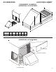
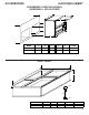
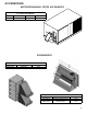
The connecting ductwork (Supply and Return) can be connected
for horizontal discharge airflow. In the down discharge applica-
tions, a matching Roof Curb is recommended.
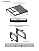
A return air filter must be installed behind the return air grille(s)
or provision must be made for a filter in an accessible location
within the return air duct. The minimum filter area should not
be less than those sizes listed in the Specification Section.
Under no circumstances should the unit be operated without
return air filters.
A 3/4" - 14 NPT drain connector is provided for removal of con-
densate water from the indoor coil. In order to provide proper
condensate flow, do not reduce the drain line size.
Refrigerant flow control is achieved by use of restrictor orifices
or thermostatic expansion valves (TXV).These models use the
FasTest Access Fitting System, with a saddle that is either
soldered to the suction and liquid lines or is fastened with a
locking nut to the access fitting box (core) and then screwed
into the saddle.
Do not remove the core from the saddle
until the refrigerant charge has been removed. Failure
to do so could result in property damage or personal in-
jury.
Single Phase - The single phase units use permanent split
capacitors (PSC) design compressors. Starting components
are therefore not required. A low MFD run capacitor assists
the compressor to start and remains in the circuit during op-
eration.
The outdoor fan motors are single phase capacitor type mo-
tors.
Air for condensing (cooling) is drawn through the outdoor coil
by a propeller fan, and is discharged vertically out the top of
the unit. The outdoor coil is designed for .0 static. No addi-
tional restriction (ductwork) shall be applied.
Conditioned air is drawn through the filter(s), field installed,
across the evaporator coil and back into the conditioned space
by the indoor blower.
COMPRESSORS
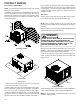
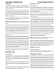
A scroll is an involute spiral which, when matched with a mat-
ing scroll form as shown, generates a series of crescent shaped
gas pockets between the two members.
During compression, one scroll remains stationary (fixed scroll)
while the other form (orbiting scroll) is allowed to orbit (but not
rotate) around the first form.
As this motion occurs, the pockets between the two forms are
slowly pushed to the center of the two scrolls while simulta-
neously being reduced in volume. When the pocket reaches
the center of the scroll form, the gas, which is now at a high
pressure, is discharged out of a port located at the center.
During compression, several pockets are being compressed
simultaneously, resulting in a very smooth process. Both the
suction process (outer portion of the scroll members) and the
discharge process (inner portion) are continuous.
Some design characteristics of the Compliant Scroll compres-
sor are:
• Compliant Scroll compressors are more tolerant of liquid
refrigerant.
NOTE: Even though the compressor section of a Scroll
compressor is more tolerant of liquid refrigerant, continued
floodback or flooded start conditions may wash oil from the
bearing surfaces causing premature bearing failure.
• These Scroll compressors use “POE” or polyolester oil
which is NOT compatible with mineral oil based lubricants
like 3GS. “POE” oil must be used if additional oil is re-
quired.
• Compliant scroll compressors perform "quiet" shutdowns
that allow the compressor to restart immediately without
the need for a time delay. This compressor will restart even
if the system has not equalized.
NOTE: Operating pressures and amp draws may differ from
standard reciprocating compressors. This information can
be found in the unit's Technical Information Manual.
INDOOR BLOWER MOTOR
GPH16M41** series model package units use a EEM (Energy
Efficient Motor) blower motor. The EEM is a 3 Phase brushless
DC (single phase AC input), ball bearing construction motor
with an integral control module with an internal FCC B EMI
filter.
The EEM is continuously powered with line voltage. The
switched 24 volt control signal is controlled by the thermostat
in the cooling, heat pump and electric heat modes.
APH16M41** series model package units use an ECM motor.
The ECM control board is factory set with the dip switch #4 in
the "ON" position for single stage units and to the "OFF" posi-
tion for the 2 stafe units. All other dip switches are factory set
in the "OFF" position. For most applications, the settings are
to be changed according to the electric heat size.
The ECM motor provides many features not available on the
traditional PSC motor. These features include:
• Improved Efficiency
• Constant CFM
• Soft Start and Stop
• Improved Humidity Control