
GPH16M Service Manual

SERVICING
32
Wiring is subject to change. Always refer to the wiring diagram on the unit for the most up-to-date wiring.
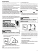
S-17D OPERATION TEST
If the voltage, capacitor, overload and motor winding test fail to
show the cause for failure:
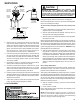
WARNING
1. Remove unit wiring from disconnect switch and wire a test
cord to the disconnect switch.
NOTE: The wire size of the test cord must equal the line wire
size and the fuse must be of the proper size and type.
2. With the protective terminal cover in place, use the three
leads to the compressor terminals that were disconnected
at the nearest point to the compressor and connect the
common, start and run clips to the respective leads.
3. Connect good capacitors of the right MFD and voltage rat-
ing into the circuit.
4. With power ON, close the switch.
WARNING
LINE VOLTAGE NOW PRESENT.
A. If the compressor starts and continues to run, the
cause for failure is somewhere else in the system.
B. If the compressor fails to start - replace.
S-18 TESTING CRANKCASE HEATER
Note: Not all compressors use crankcase heaters.
The crankcase heater must be energized a minimum of twenty-
four (24) hours before the compressor is operated.
Crankcase heaters are used to prevent migration or accumula-
tion of refrigerant in the compressor crankcase during the off
cycles and prevents liquid slugging or oil pumping on start up.
On some models, the crankcase heater is controlled by a crank-
case heater thermostat that is wired in series with the crank-
case heater.
A crankcase heater will not prevent compressor damage due
to a floodback or over charge condition.
WARNING
DISCONNECT POWER SUPPLY BEFORE SERVICING.
1. Disconnect the heater lead wires.
2. Using an ohmmeter, check heater continuity - should test
continuous, if not, replace.
S-18A CHECKING CRANKCASE HEATER
THERMOSTAT
Note: Not all models with crankcase heaters will have a
crankcase heater thermostat.
1. Install a thermocouple type temperature test lead on the
discharge line adjacent to the crankcase heater thermo-
stat.
2. Check the temperature at which the control closes its con-
tacts by lowering the temperature of the control. The crank-
case heater thermostat should close at 67°F ± 5°F.
3. Check the temperature at which the control opens its con-
tacts by raising the temperature of the control. The crank-
case heater thermostat should open at 85°F ± 5°F.
4. If not as above, replace control.
S-21 CHECKING REVERSING VALVE AND
SOLENOID
Occasionally the reversing valve may stick in the heating or
cooling position or in the mid-position.
When stuck in the mid-position, part of the discharge gas from
the compressor is directed back to the suction side, resulting
in excessively high suction pressure. An increase in the suc-
tion line temperature through the reversing valve can also be
measured. Check operation of the valve by starting the sys-
tem and switching the operation from COOLING to HEATING
cycle.
If the valve fails to change its position, test the voltage (24V) at
the valve coil terminals, while the system is on the COOLING
cycle.
If no voltage is registered at the coil terminals, check the op-
eration of the thermostat and the continuity of the connecting
wiring from the "O" terminal of the thermostat to the unit.
If voltage is registered at the coil, tap the valve body lightly
while switching the system from HEATING to COOLING, etc.
If this fails to cause the valve to switch positions, remove the
coil connector cap and test the continuity of the reversing valve
solenoid coil. If the coil does not test continuous - replace it.
If the coil test continuous and 24 volts is present at the coil
terminals, the valve is inoperative - replace it.