
GPH16M Service Manual

SERVICING
33
S-24 TESTING DEFROST CONTROL
NOTE: PCBDM133 defrost control has a three (3) minute
compressor off cycle delay.
NOTE: The PCBDM133 defrost control is shipped from the
factory with the compressor delay option selected. This will
de-energize the compressor contactor for 30 seconds on defrost
initiation and defrost termination. If the jumper is set to Normal,
the compressor will continue to run during defrost initiation
and defrost termination. The control will also ignore the low
pressure switch connected to R-PS1 and PS2 for 5 minutes
upon defrost initiation and 5 minutes after defrost termination.
To check the defrost control for proper sequencing, proceed as
follows: With power ON; unit not running.
1. Jumper defrost thermostat by placing a jumper wire across
the terminals "DFT" and "R-DFT" at defrost control board.
2. Connect jumper across test pins on defrost control board.
3. Set thermostat to call for heating. System should go into
defrost within 21 seconds.
4. Immediately remove jumper from test pins.
5. Using VOM check for voltage across terminals "C & "O-
RV". Meter should read 24 volts.
6. Using VOM check for voltage across fan terminals DF1
and DF2 on the board. You should read line voltage (208-
230 VAC) indicating the relay is open in the defrost mode.
7. Using VOM check for voltage across "W" & "C" terminals
on the board. You should read 24 volts.
8. If not as above, replace control board.
9. Set thermostat to off position and disconnect power before
removing any jumpers or wires.
NOTE: Remove jumper across defrost thermostat before re-
turning system to service.
S-25 TESTING DEFROST THERMOSTAT
1. Install a thermocouple type temperature test lead on the
tube adjacent to the defrost control. Insulate the lead point
of contact.
2. Check the temperature at which the control closes its con-
tacts by lowering the temperature of the control. The de-
frost control should close at 34°F ± 5°F.
3. Check the temperature at which the control opens its con-
tacts by raising the temperature of the control. The defrost
control should open at 60°F ± 5°F.
4. If not as above, replace control.
S-50 CHECKING HEATER LIMIT CONTROL(S)
(OPTIONAL ELECTRIC HEATERS)
Each individual heater element is protected with an automatic
rest limit control connected in series with each element to
prevent overheating of components in case of low airflow. This
limit control will open its circuit at approximately 150°F. to
160°F and close at approximately 110°F.
WARNING
DISCONNECT ELECTRICAL POWER SUPPLY.
1. Remove the wiring from the control terminals.
2. Using an ohmmeter test for continuity across the normally
closed contacts. No reading indicates the control is open
- replace if necessary. Make sure the limits are cool before
testing.
IF FOUND OPEN - REPLACE - DO NOT WIRE AROUND.
S-52 CHECKING HEATER ELEMENTS
Optional electric heaters may be added, in the quantities shown
in the spec sheet for each model unit, to provide electric resis-
tance heating. Under no condition shall more heaters than the
quantity shown be installed.
WARNING
1. Disassemble and remove the heating element(s).
2. Visually inspect the heater assembly for any breaks in the
wire or broken insulators.
3. Using an ohmmeter, test the element for continuity - no
reading indicates the element is open. Replace as neces-
sary.
S-100 REFRIGERATION REPAIR PRACTICE
DANGER
ALWAYS REMOVE THE REFRIGERANT CHARGE IN
A PROPER MANNER BEFORE APPLYING HEAT TO
THE SYSTEM.
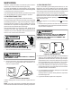
These models use the FasTest Access Fitting System, with a
saddle that is either soldered to the suction and liquid lines or
is fastened with a locking nut to the access fitting box (core)
and then screwed into the saddle. Do not remove the core
from the saddle until the refrigerant charge has been
removed. Failure to do so could result in property dam-
age or personal injury.
When installing a new core or reinstalling the core after re-
moval, it is very important to note that before inserting the core
into the saddle, the core and saddle must be free of debris and
the “O” Ring
must have a thin coating of refrigerant oil applied
to it. The oil is to prevent the “O” Ring from being deformed