
GPH16M Service Manual

SERVICING
37
1. Attach an accurate thermometer or preferably a thermo-
couple type temperature tester to the liquid line close to
the high pressure access fitting process tube.
2. Install a high side pressure gauge on the high side (liquid)
access fitting.
3. Record the gauge pressure and the temperature of the line.
4. Review the technical information manual or specification
sheet for the model being serviced to obtain the design
subcooling.
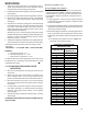
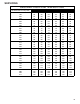
5. Compare the hi-pressure reading to the "Required Liquid
Line Temperature" chart . Find the hi-pressure value on the
left column. Follow that line right to the column under the
design subcooling value. Where the two intersect is the
required liquid line temperature.
Alternately you can convert the liquid line pressure gauge
reading to temperature by finding the gauge reading in Tem-
perature - Pressure Chart and reading to the left, find the
temperature in the °F. Column.
6. The difference between the thermometer reading and pres-
sure to temperature conversion is the amount of subcooling.
Add charge to raise subcooling. Recover charge to lower
subcooling.
SUBCOOLING = SAT. LIQUID TEMP. - LIQUID LINE TEMP.
EXAMPLE:
a. Liquid Line Pressure = 417
b. Corresponding Temp. °F. = 120°
c. Thermometer on Liquid line = 113°F.
To obtain the amount of subcooling subtract 113°F from 120°F.
The difference is 7° subcooling, which would fall in the
+ range
of allowable subcooling.
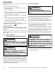
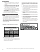
S-110 CHECKING EXPANSION VALVE
OPERATION
1. Remove the remote bulb of the expansion valve from the
suction line.
2. Start the system and cool the bulb in a container of ice
water, closing the valve. As you cool the bulb, the suction
pressure should fall and the suction temperature will rise.
3. Next warm the bulb in your hand. As you warm the bulb,
the suction pressure should rise and the suction tempera-
ture will fall.
4. If a temperature or pressure change is noticed, the expan-
sion valve is operating. If no change is noticed, the valve is
restricted, the power element is faulty, or the equalizer
tube is plugged.
5. Capture the charge, replace the valve and drier, evacuate
and recharge.
SUPERHEAT AND SUBCOOLING ADJUSTMENT ON TXV
APPLICATIONS
EXPANSION V ALVE (TXV) SYSTEM
Two Speed Application (APH16)
Run the unit on high stage cooling for 10 minutes until
refrigerant pressures stabilize. Follow the guidelines and
methods below to check unit operation and ensure that
the refrigerant charge is within limits. Charge the unit on
high stage.
1. Purge gauge lines. Connect service gauge manifold to
access fittings. Run system at least 10 minutes to allow
pressure to stabilize.
2. Temporarily install thermometer on liquid (small) line near
liquid line access fitting with adequate contact and insu-
late for best possible reading.
3. Check subcooling and superheat. Two stage systems run-
ning on high stage with TXV application should have a
subcooling and superheat within the range listed on the
chart.
a. If subcooling and superheat are low, adjust TXV
superheat, then check subcooling.
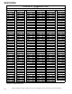
SUCTION PRESSURE
SATURATED SUCTION
TEMPERATURE ºF
PSIG R-410A
50 1
52 3
54 4
56 6
58 7
60 8
62 10
64 11
66 13
68 14
70 15
72 16
74 17
76 19
78 20
80 21
85 24
90 26
95 29
100 31
110 36
120 41
130 45
140 49
150 53
160 56
170 60
SATURATED SUCTION PRESSURE
TEMPERATURE CHART