
Installation Manual

14
ELECTRICAL ADJUSTMENTS
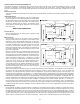
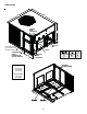
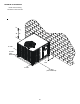
This series of electric cooling and, heat pump package equipment is designed to accept a field installed electric heat kit. The unit
is equipped to easily install the HKP or HKR Series Electric Heat Kit. Full Installation Instructions are included in this kit. Please
use this document for guidance in field equipping the package unit with electric heat.
Choose the heat kit that fits the application for the specific installation. Permanently mark the unit’s nameplate with the model
being installed. High and low voltage connections are detailed in the heat kit instructions.
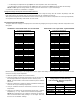
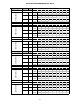
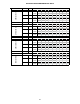
Indoor Blower motor speed tap selection may need to be modified to accommodate normal continuous operation to prevent a
nuisance trip. See following table.
MAINTENANCE
The Self Contained Package Air Conditioner and Heat Pump should operate for many years without excessive service calls if the
unit is installed properly. However it is recommended that the homeowner inspect the unit before a seasonal start up. The coils
should be free of debris so adequate air flow is achieved. The return and
supply registers should be free of any obstructions. The filters should be
cleaned or replaced. These few steps will help to keep the product up time to a
maximum. The Troubleshooting Chart (see Appendix) should help in identifying
problems if the unit does not operate properly.
Refer to Blower Performance section in the Appendix - Higher air flow
lowers temperature rise.
Lower air flow raises temperature rise.
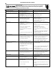
SERVICE
THE FOLLOWING INFORMATION IS FOR USE BY QUALIFIED SERVICE
AGENCY ONLY: OTHERS SHOULD NOT ATTEMPT TO SERVICE THIS EQUIPMENT.
COMMON CAUSES OF UNSATISFACTORY OPERATION OF HEAT
PUMP ON THE HEATING CYCLE
INADEQUATE AIR VOLUME THROUGH INDOOR COIL
When a heat pump is in the heating cycle, the indoor coil is func-
tioning as a condenser. The return air filter must always be clean,
and sufficient air volume must pass through the indoor coil to
prevent excessive discharge pressure, and high pressure cut
out.
OUTSIDE AIR INTO RETURN DUCT
Do not introduce cold outside air into the return duct of a heat pump installation. Do not allow air entering the indoor coil to drop below
65°F. Air below this temperature will cause low discharge pressure, thus low suction pressure, and excessive defrost cycling resulting
in low heating output. It may also cause false defrosting.
UNDERCHARGE
An undercharged heat pump on the heating cycle will cause low discharge pressure resulting in low suction pressure and frost
accumulation on the outdoor coil.
POOR “TERMINATING” SENSOR CONTACT
The unit’s defrost terminating sensor must make good thermal contact with the outdoor coil tubing. Poor contact may not terminate the
unit’s defrost cycle quickly enough to prevent the unit from cutting out on high discharge pressure.
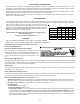
MALFUNCTIONING REVERSING VALVE - THIS MAY BE DUE TO:
1. Solenoid not energized - In order to determine if the solenoid is energized, touch the nut that holds the solenoid cover in place
with a screwdriver. If the nut magnetically holds the screwdriver, the solenoid is energized and the unit is in the cooling cycle.
2. No voltage at unit’s solenoid - Check unit voltage. If no voltage, check wiring circuit.
3. Valve will not shift:
a. Undercharged - check for leaks;
b. Valve Body Damaged - Replace valve;
c. Unit Properly Charged - If it is on the heating cycle, raise the discharge pressure by restricting air flow through the indoor
coil. If the valve does not shift, tap it lightly on both ends with a screwdriver handle. DO NOT TAP THE VALVE BODY. If the unit
is on the cooling cycle, raise the discharge pressure by restricting air flow through the outdoor coil. If the valve does not shift
after the above attempts, cut the unit off and wait until the discharge and suction pressure equalize, and repeat above steps.
If the valve does not shift, replace it.
MODEL
5 8 10 15 20
GPH1624M41
333xx
GPH1630M41
3333x
GPH1636M41
3333x
GPH1642M41
3333x
GPH1648M41
33333
All models are factory shipped at T3 speed
ELECTRIC HEAT kW